Miky's CNC6040 2017 Project
Last updated 15/12/2017
What's my CNC project - 2017
I though a bench-top CNC would be a great add-on tool to my Jewelry making 'hobby'. I can think of a million fun things to do with it, not just in the field of jewelry.
2 ways to go about it, if money is not an issue, just buy a plug and play unit from a reputable distributor, which comes with computer to run it, software, support and all, including a price tag larger than an average yearly wage.
But if you can't justify the expense like myself, you can still try to do it all on the cheap and get yourself a very decent setup but it requires a bit more work, efforts and patience !.
After much research, I worked out that the machine itself is only half the battle, being able to use it to do the things I've seen other people do, will not happen overnight, it will be a steep learning curve and I'll have to be patient.
In short, I'll give it a shot, the 'project' is to put together a good small CNC setup with a small budget and slowly learn to make goodies with it and incorporate it in the jewelery making field. Engraving is the first thing that comes to mind, texturing, carving, cutting pierced pieces, molds, wax carving. I could also attached a laser head and ... and ... and.. you get the idea :-).
Why this page ?
The obvious, to add to the pool of data available to people with same interests. I strugeled to find enough info about the Novusun NVEM Mach3 CNC motion board so i want to share my findings and feedback about it.
The Plan (December 2016)
There was some cheap Chinese made 300mm x 400mm 3 Axis CNC with 200w/400w spindles and LPT controllers on Ebay that would have been just fine to do engraving and light milling but i want something a bit better that i won't have to change in a hurry.
I ended up choosing a :
4 axis, 6040 (60cm x 40cm table) , 1.5kw water cooled spindle , LPT port controller & VFD
I wanted one with a USB controller and home switches but the price was jumping high over my budget.
I came across many posts from people saying Chinese CNCs are wired with poor quality cables, low quality LPT breakout boards causing missed steps etc... Apparently the way to go is to re-wire them with better quality shielded cables, add home and limit switches and replace the breakout board with a USB or Ethernet motion control Board.
On the other hand , some people report having absolutely no problems with the out of the box configuration.
In the doubt.... i'll try removing possible problems from the start.
So the plan is:
- Order the CNC
- Install & wire 6 switches, re-place all cabling and install a motion control board. Ethernet Motion control boards are rather new and apparently the best ones but a popular one is AU$400 or so. I came across a Chinese one "Novusun NVEM" it seems really good for AU$155. I couldn't find much feedback/posts from people using this board so i decided to just get it and see what happens .
- I will also need a desk or bench to put the machine on, a cheap computer , a cheap screen, some cutting/milling bits. A Z axis probe And i wouldn't mind one of those fancy Mach3 wireless controller.
- Install and setup Mach3
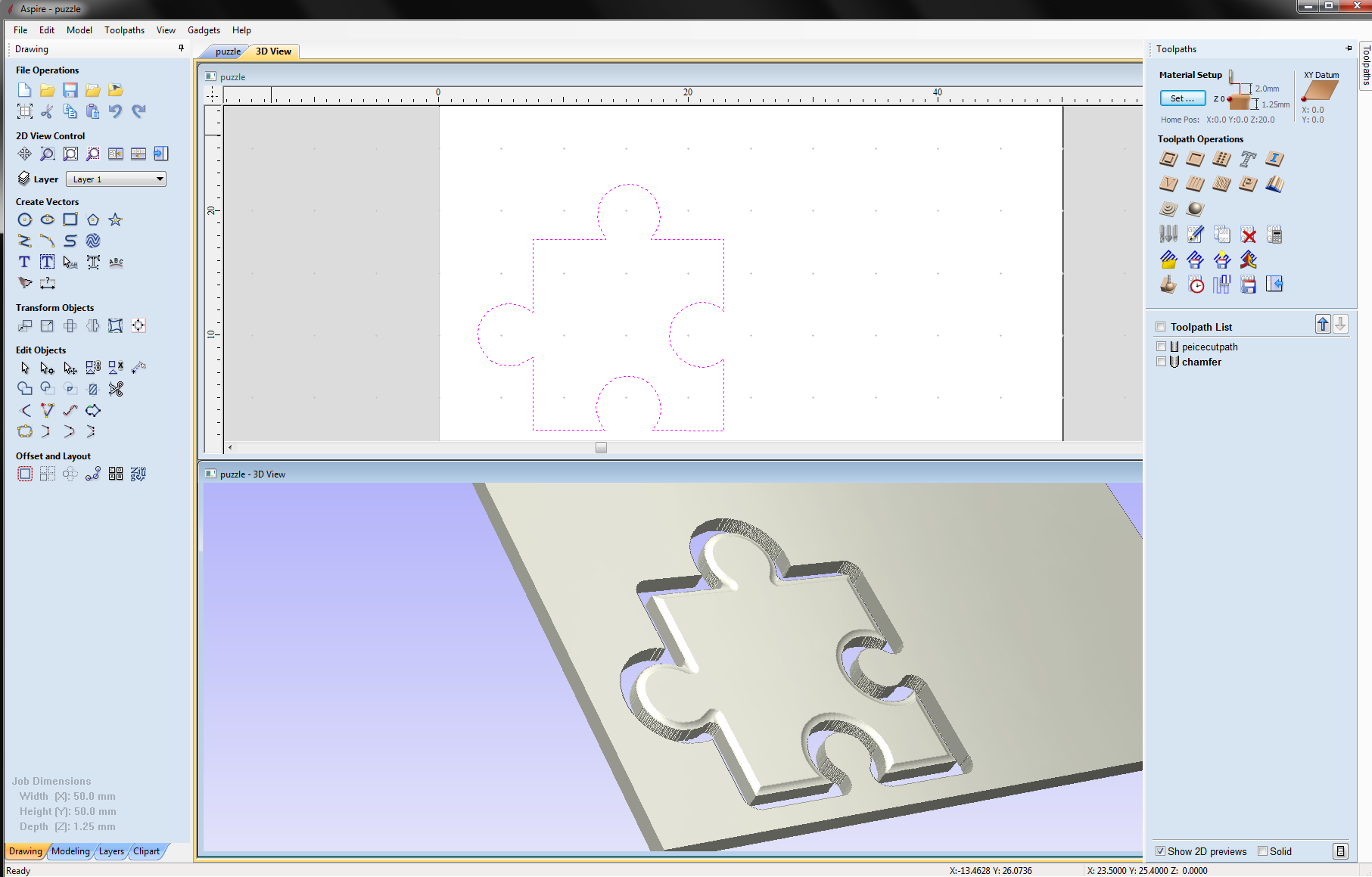
- Get Aspire Vectrics and start learning :-) So far It seems to be the most adapted to 'artistic' needs .
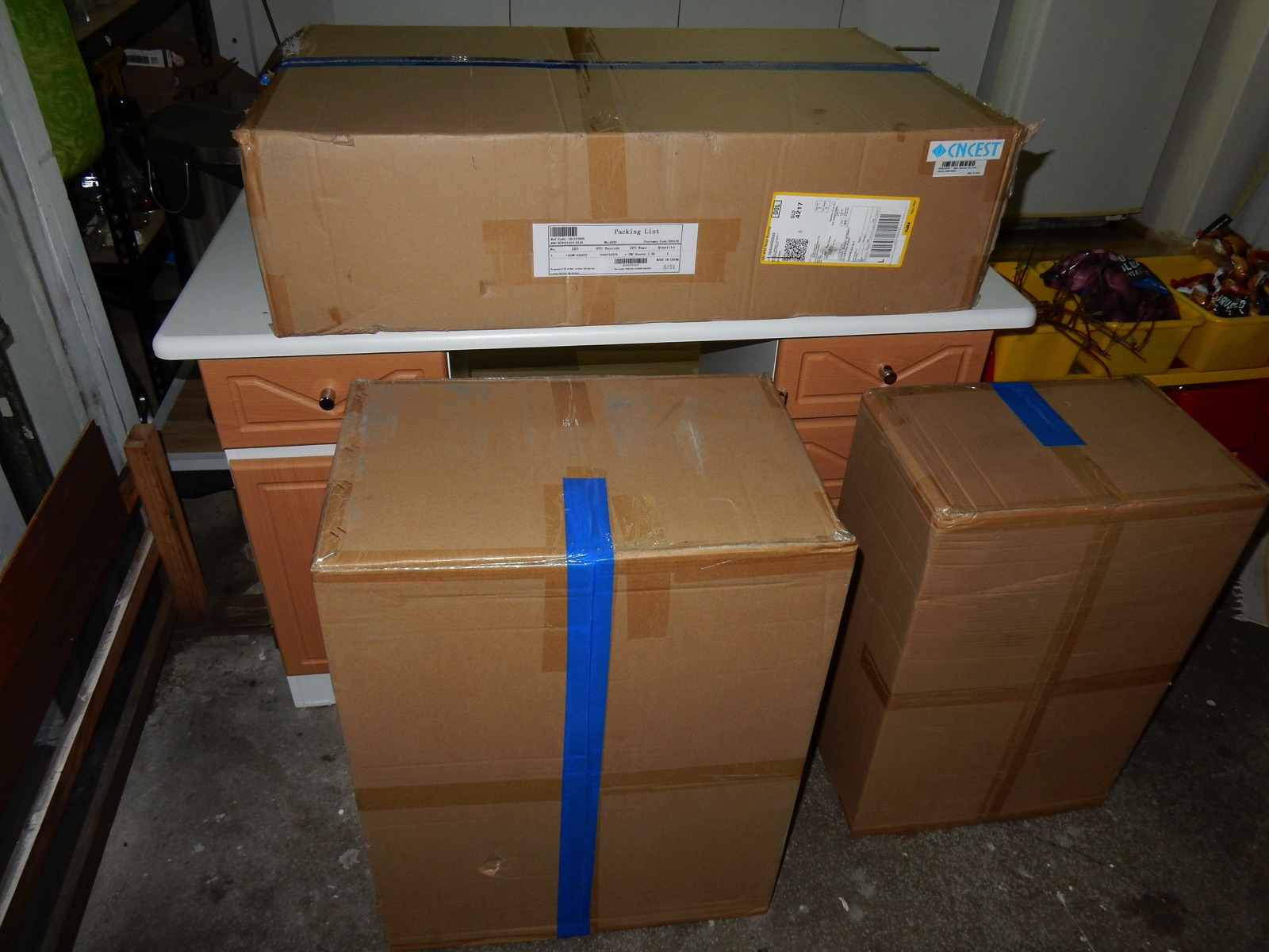
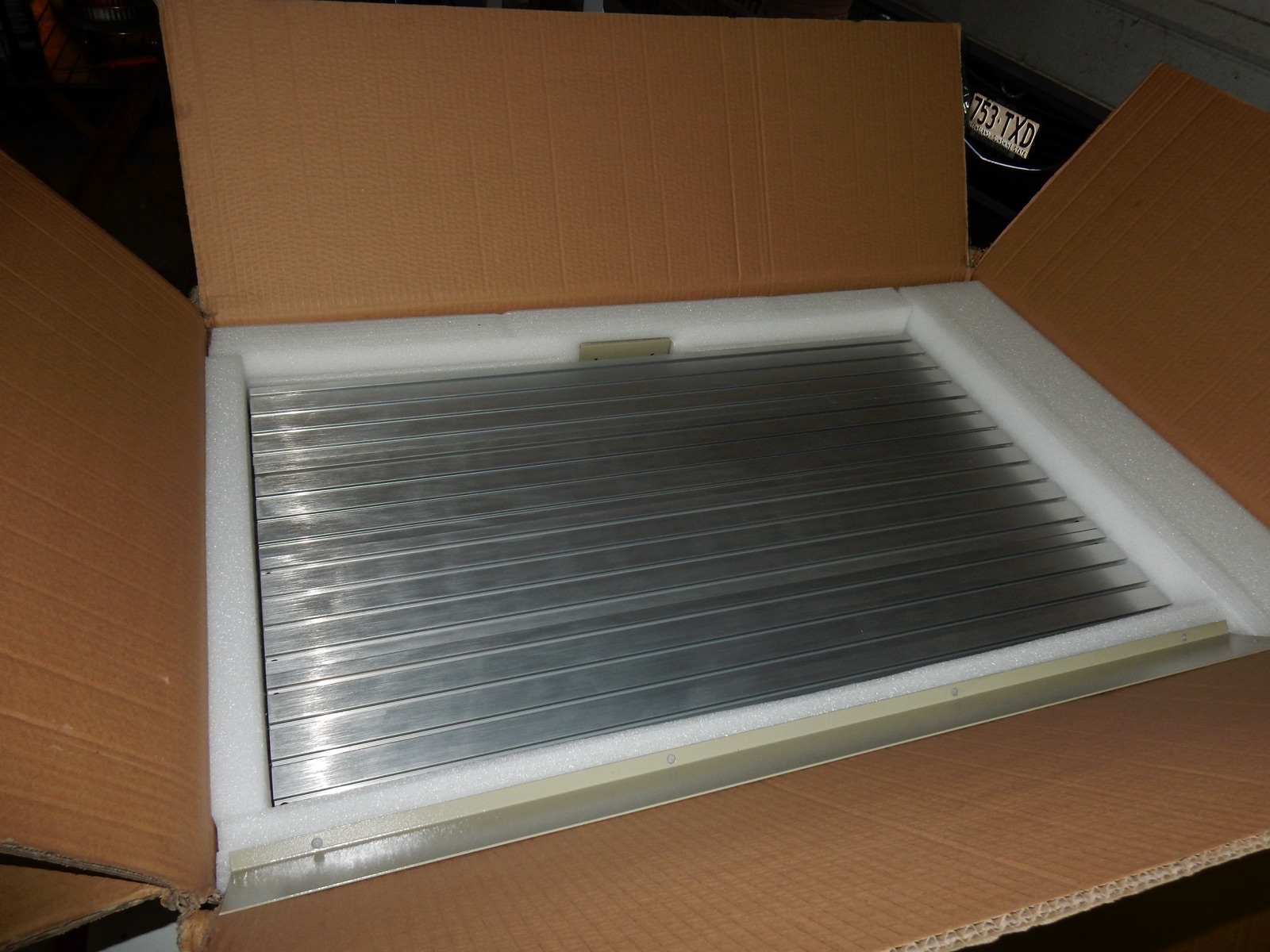
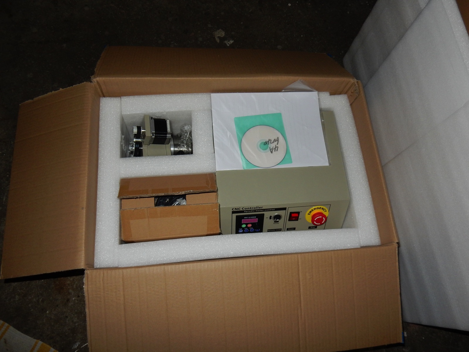
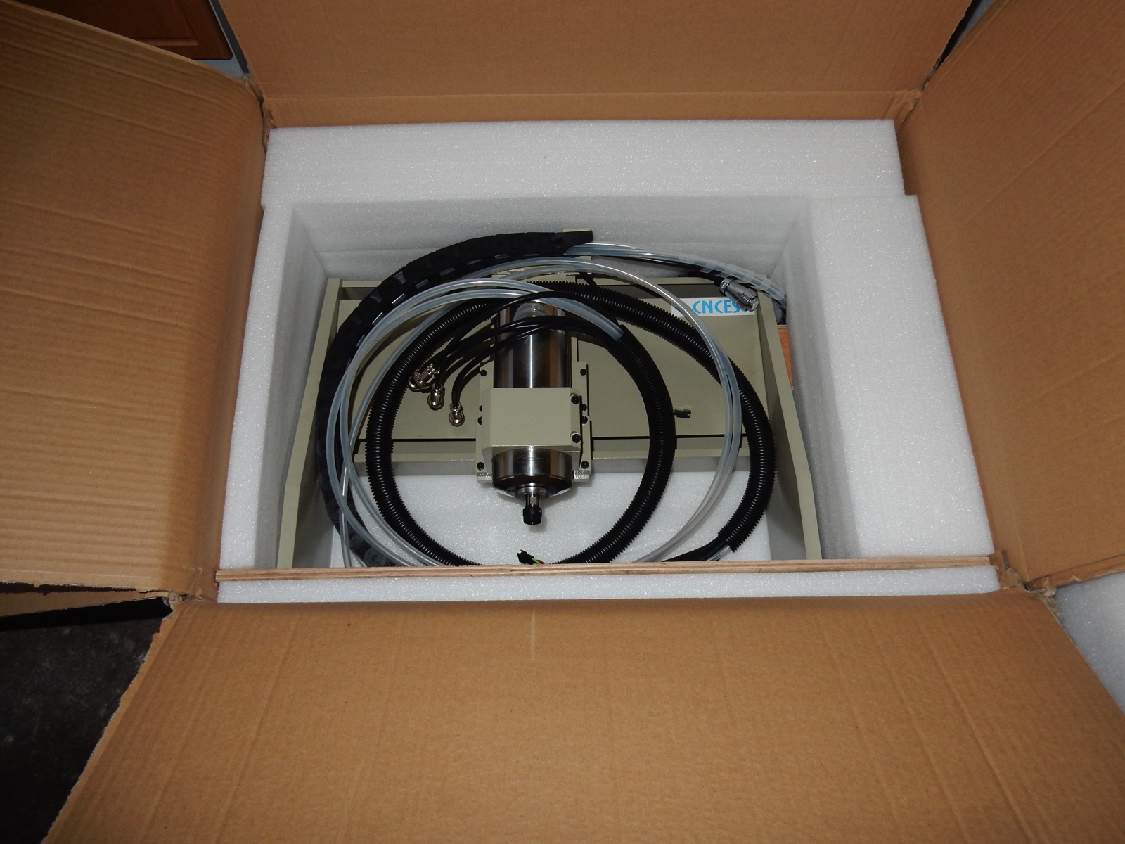
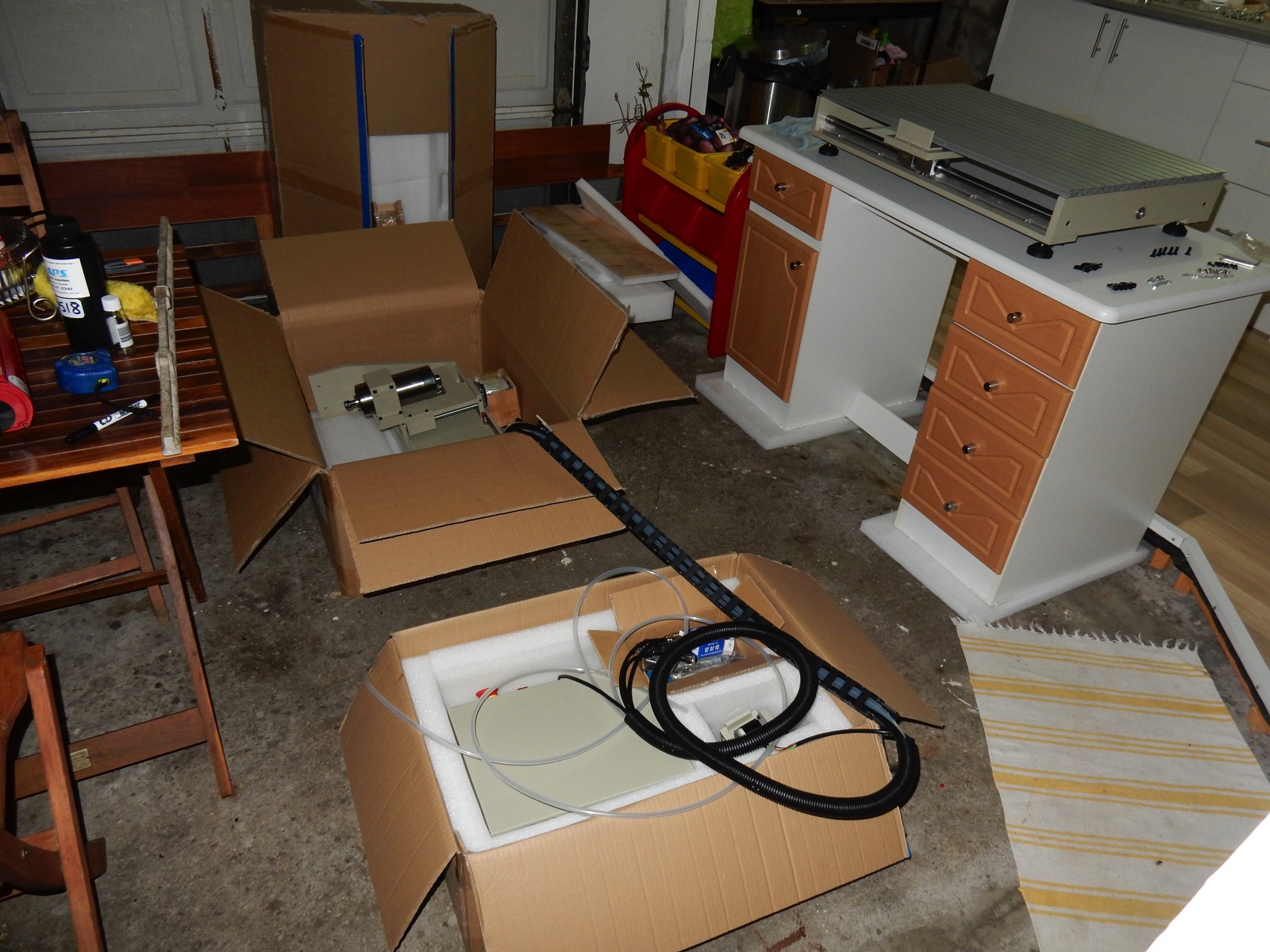
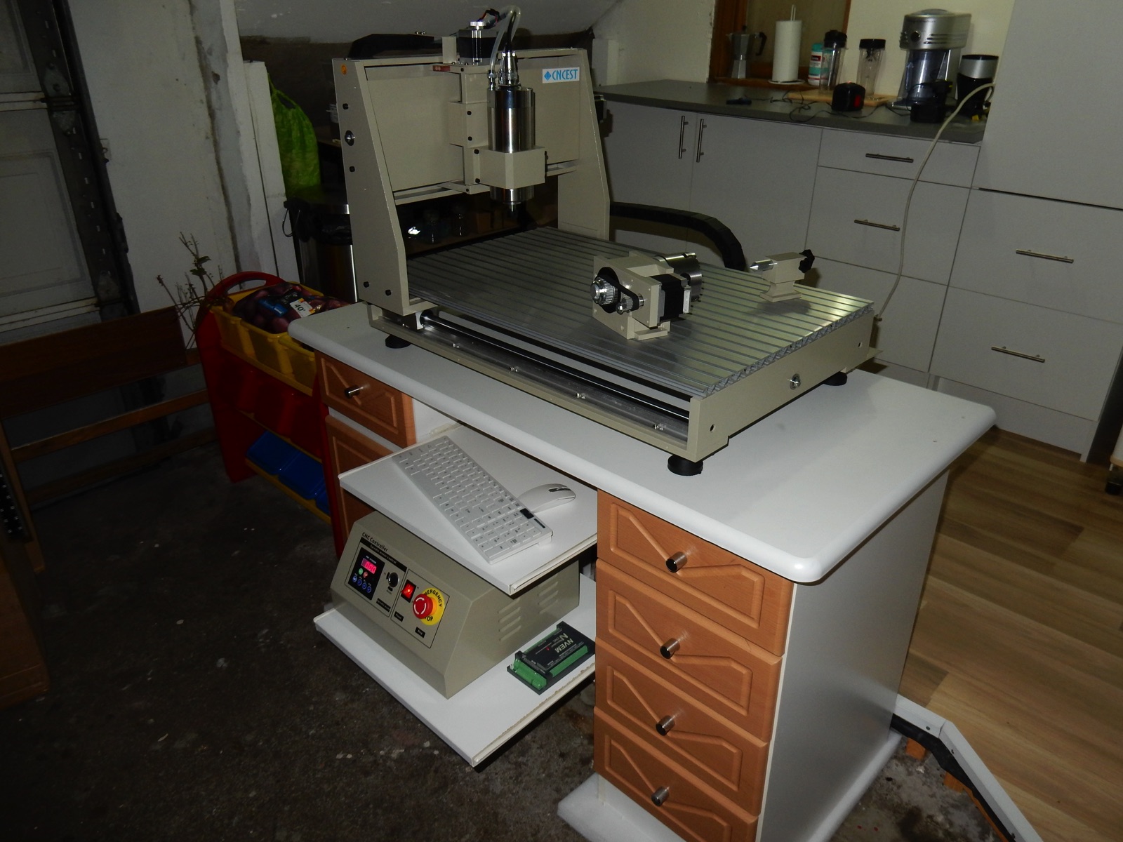
Step 1 - The CNC arrived!! lets open the boxes (27 Jan 2017)
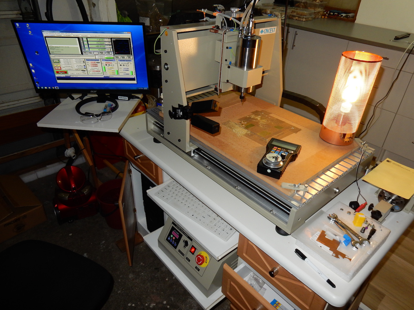
3 Boxes, 58Kg a lot bigger and heavier than I thought! How exciting though :-P . My mate also found a free desk on the street , just next door! I think i can use it, i'll add couple of sliding shelves for the keyboard and controller :-)
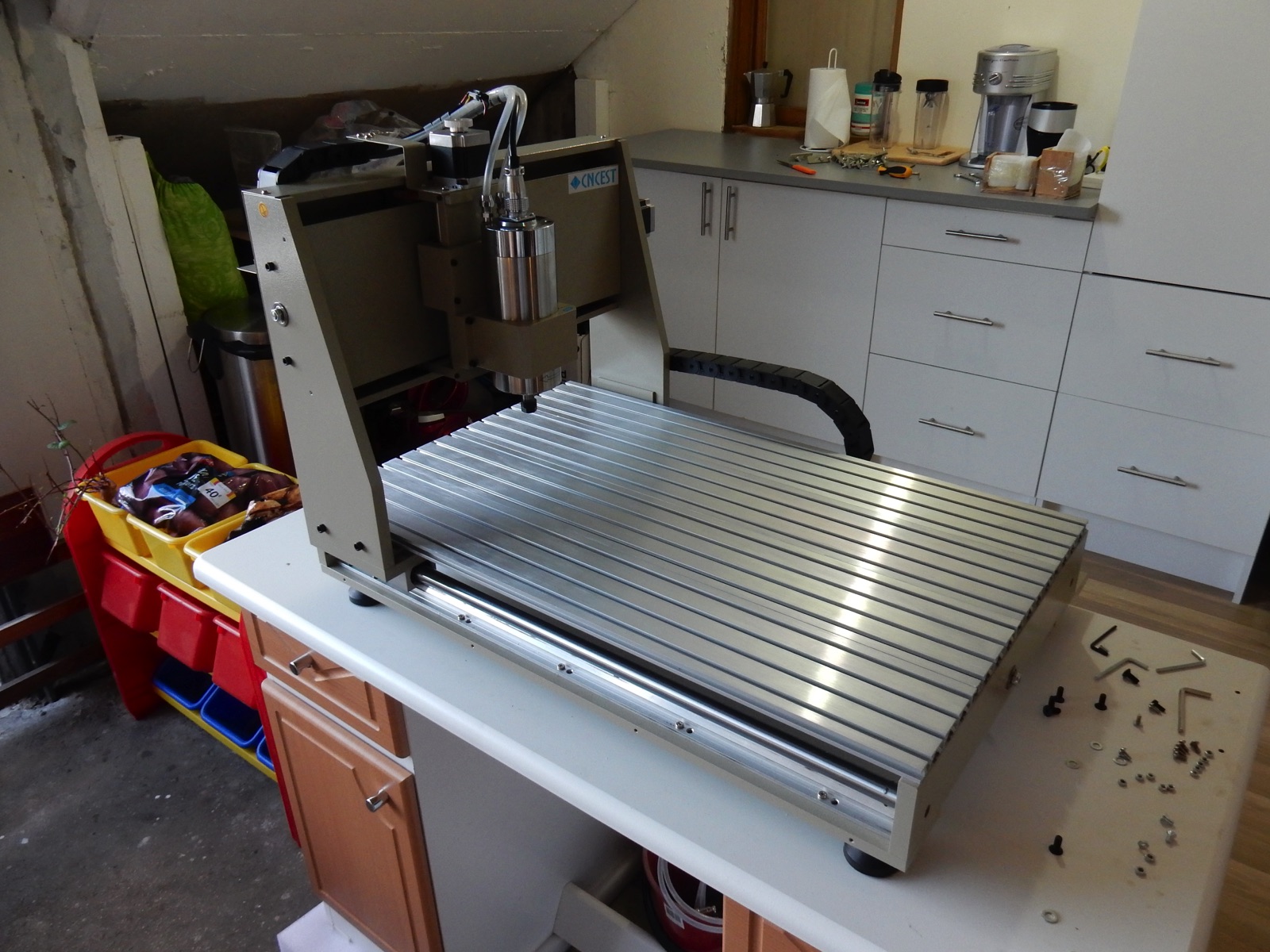
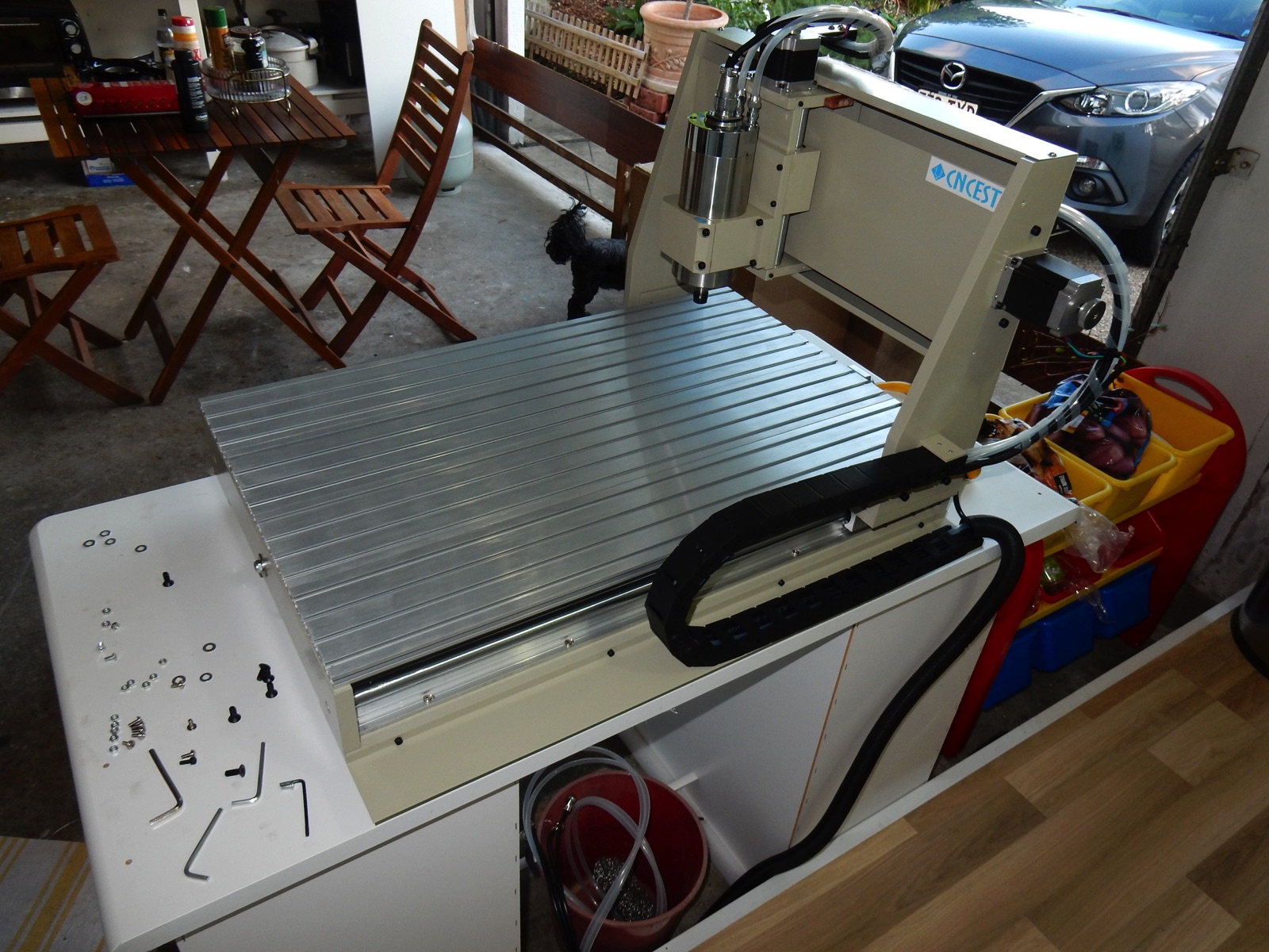
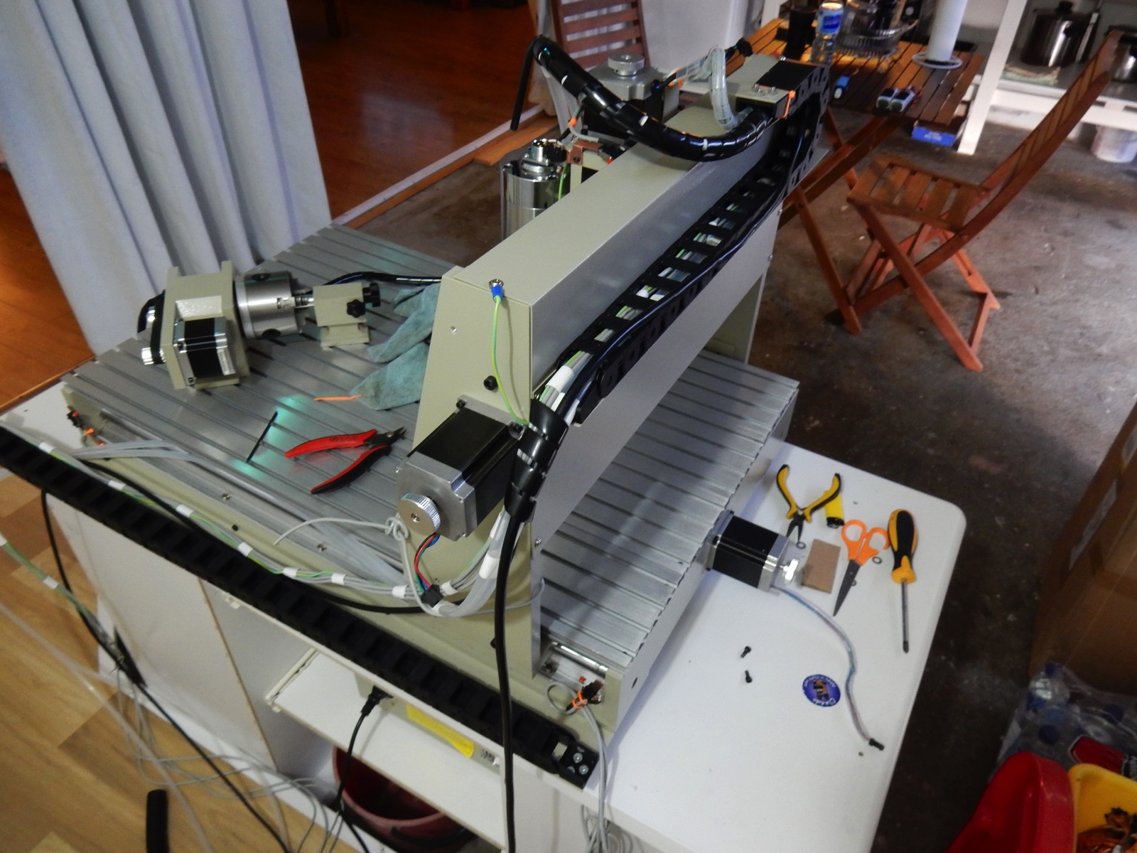
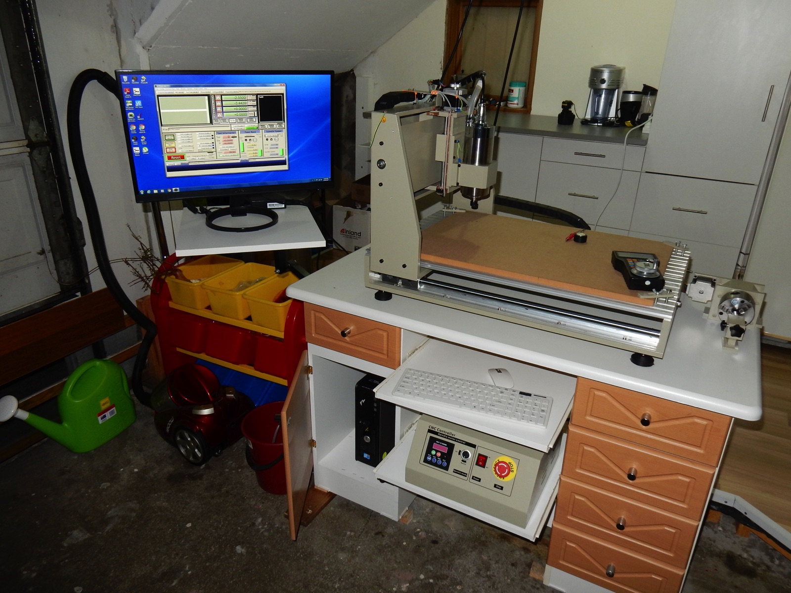
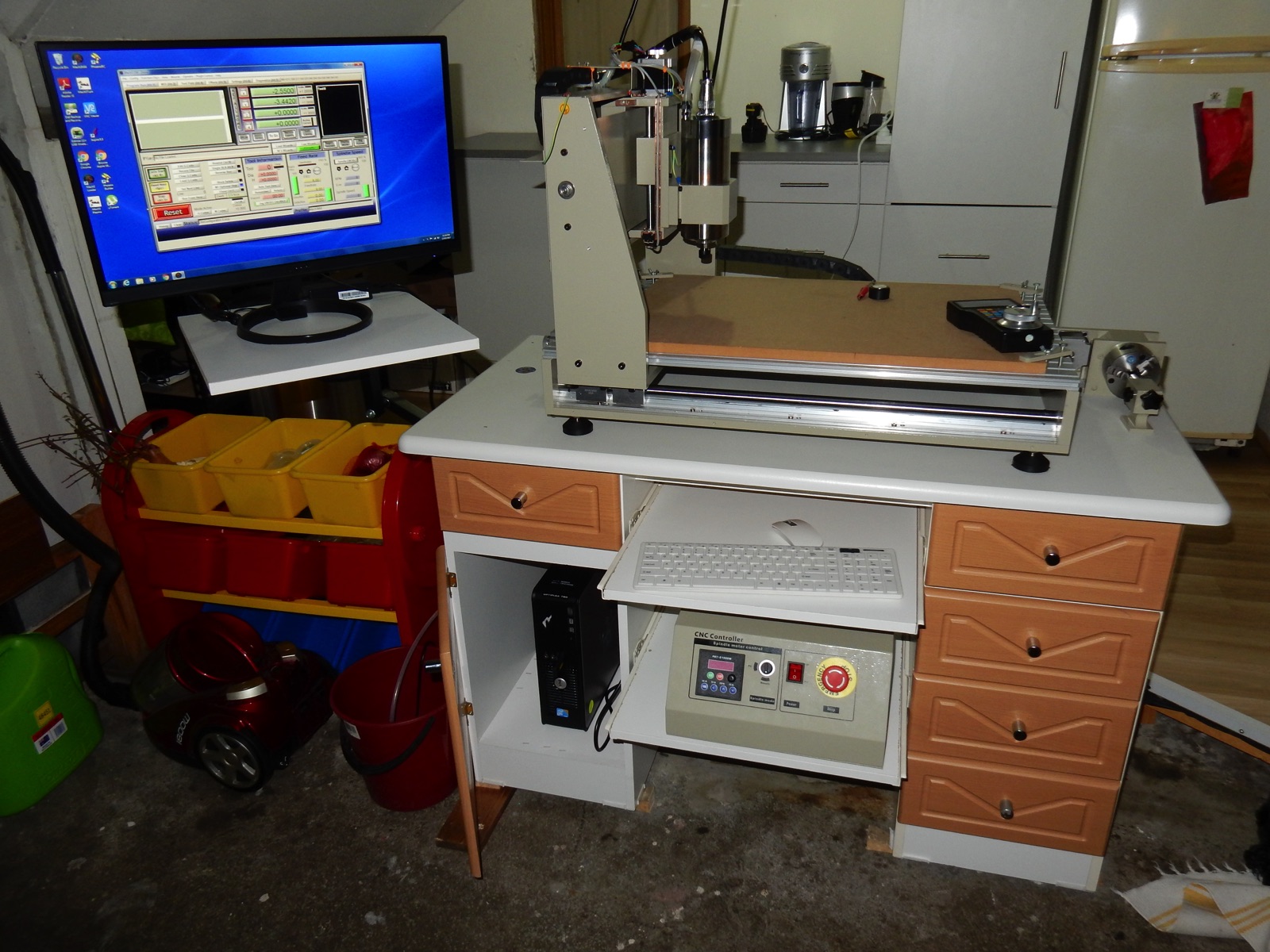
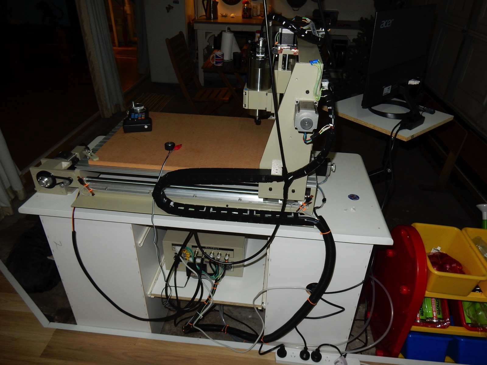
Step 2 - Putting the bits together
Quite happy with quality of the frame, very steady. No instructions and plenty of extra screws but simple enough. I built a couple of sliding shelve on the desk, it will work out good i think. I got a cheap keyboard/mouse but no computer yet.
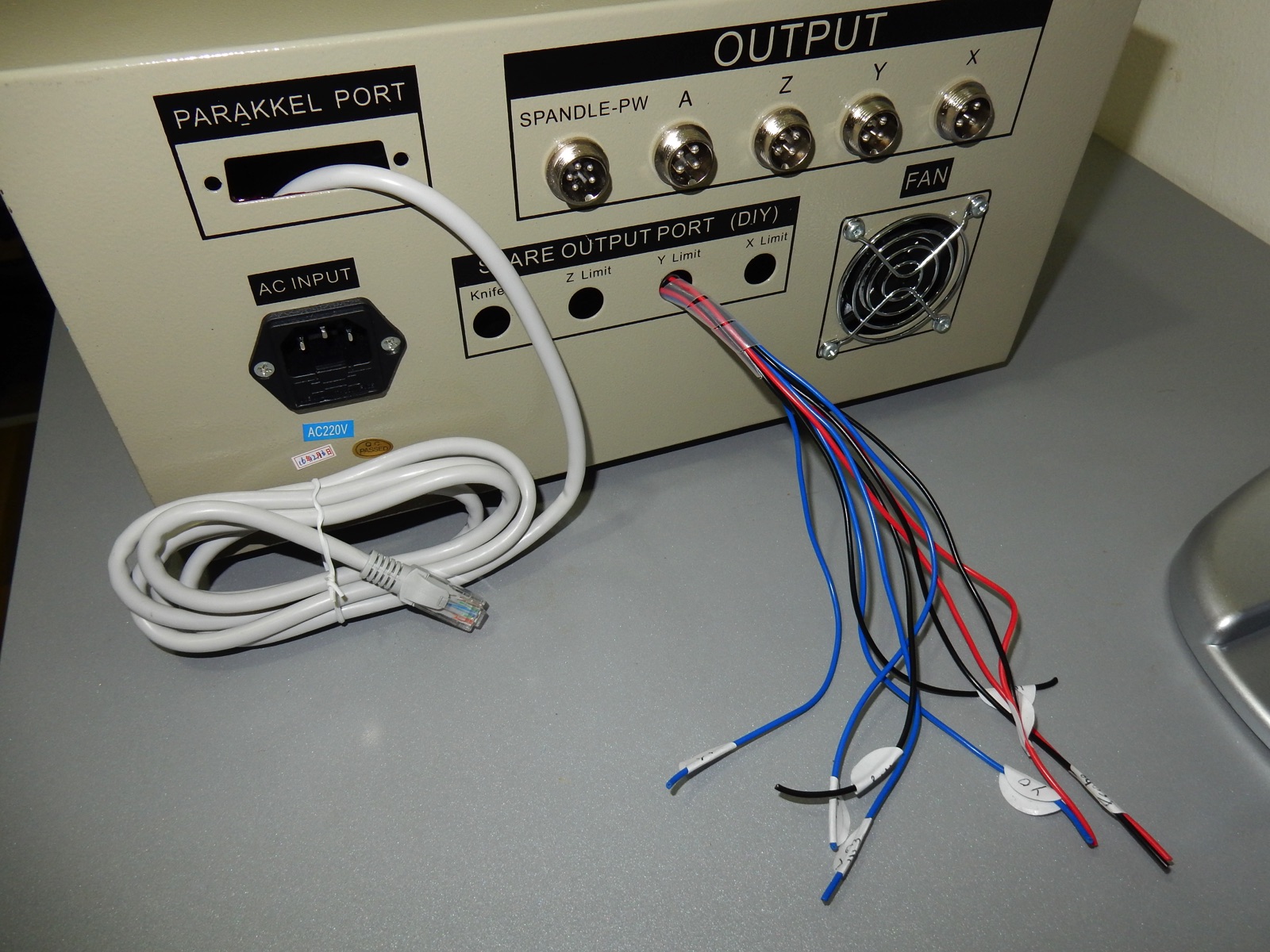
My electrical background hasn't faded away completely yet so i had a good look at the cabling and opened the controller box to check out if i could fit the new board in it. OK, the cables are not shielded but they are of good quality , i don't think they would split in a hurry like some people mentioned. The quality of the wiring, soldering in plugs etc.. is impeccable way better than i was expecting. Cheap break out board but the stepper motor drivers are not too bad, so is the VFD.
Ironically the only problems i could see are the most basic ones ! The Spindle cable running along the stepper motor cables is not the best idea and could be a source of interference.... and ...
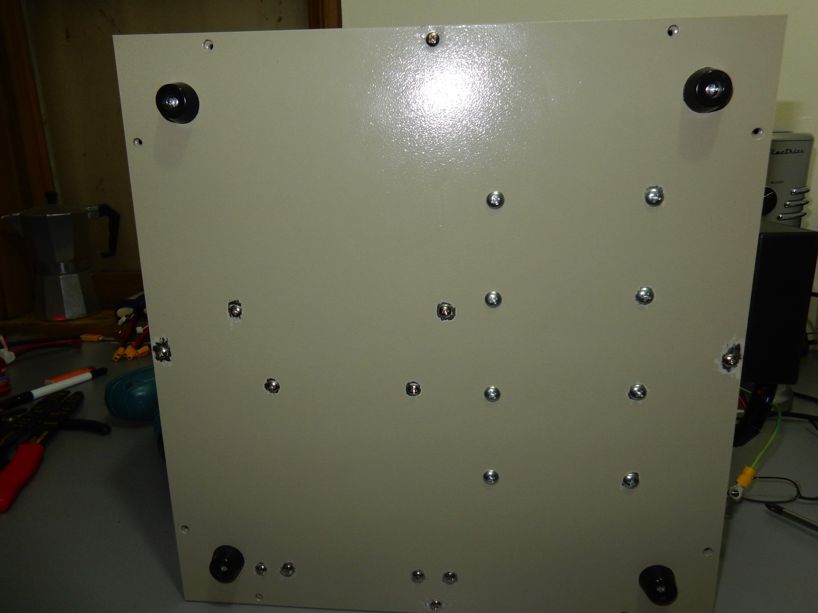
There is no ground continuity , none , nothing , neither on the frame itself nor within the controller box. The paint job is so good and thick, even in the screw holes that every single panel or component is isolated ! not all those Chinese CNC are built the same , not all have painted frames, but most have painted controller boxes. If nothing is grounded in the controller, i can imagine the magnetic interferences from the VFD traveling straight through the stepper motor drivers, power supply, breakout board that probably accounts for many of the problems people are having.
In other words i think changing cables and all is probably over the top, scratching a bit of pain under a few screw and pulling the spindle cable out of the cable rack away from the stepper motor and switch cables and those CNC should run real good.
But i already bought the shielded cable and i have to undo everything to put the switches cables in so I may as well change the stepper motor cables in the process :-/
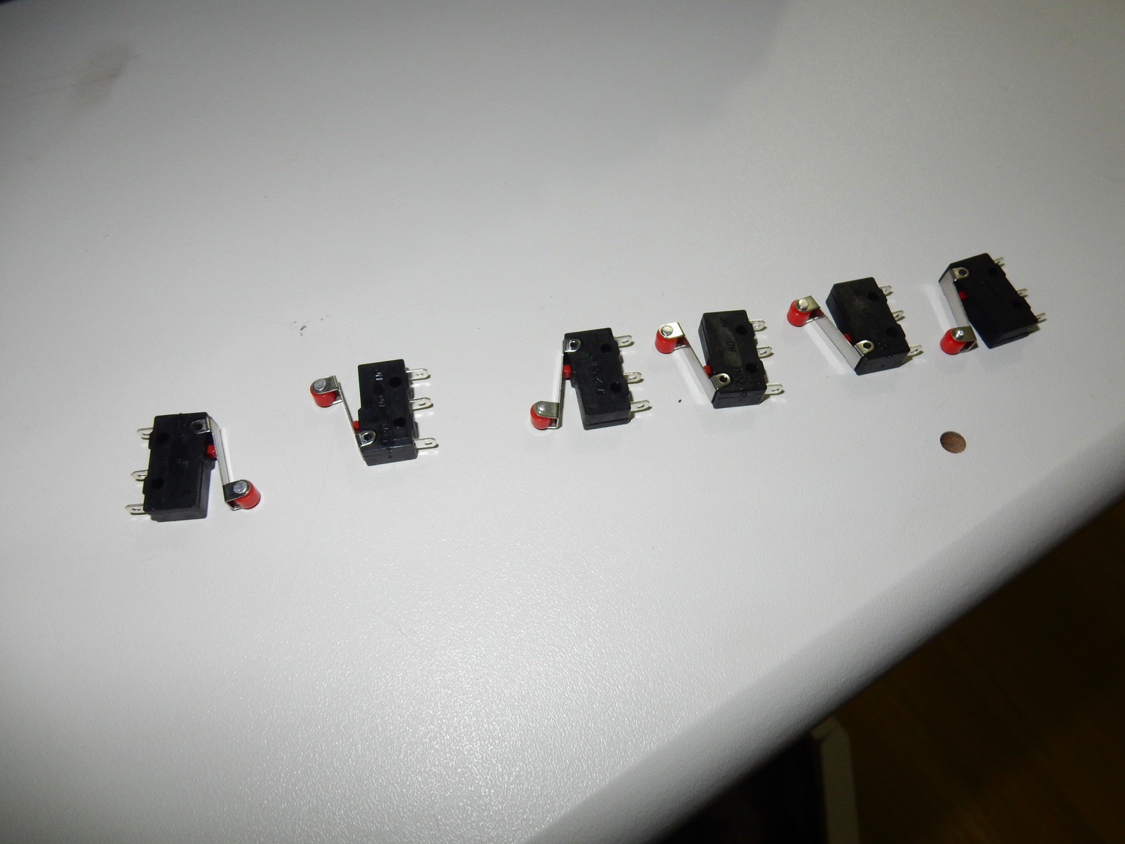
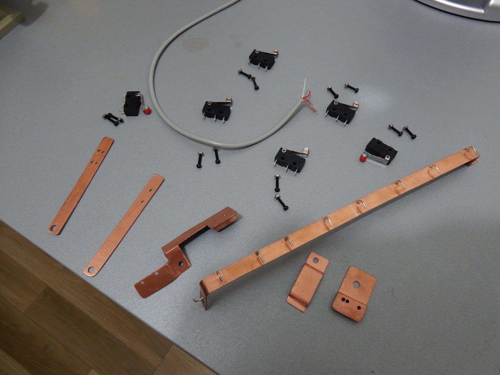
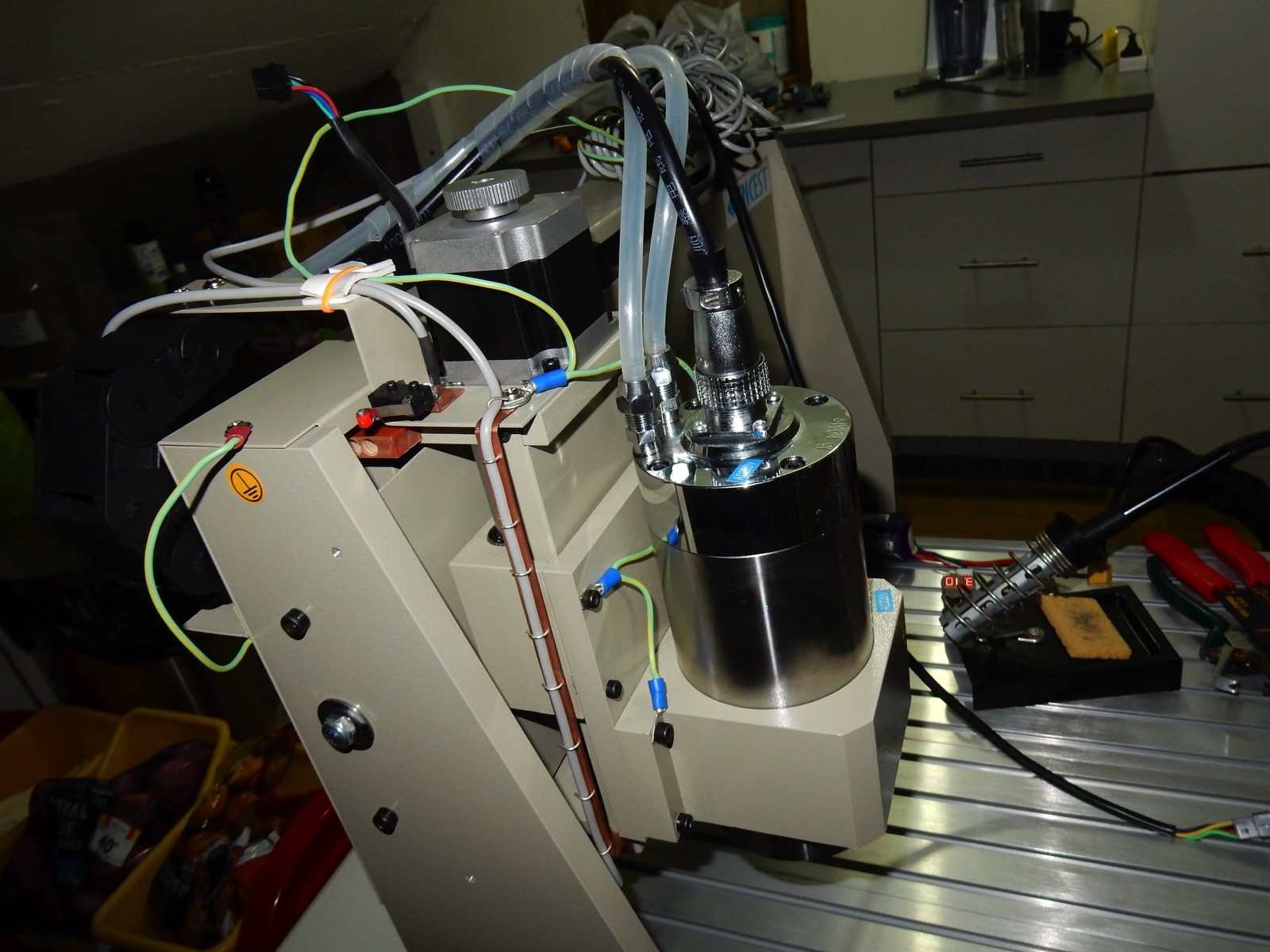
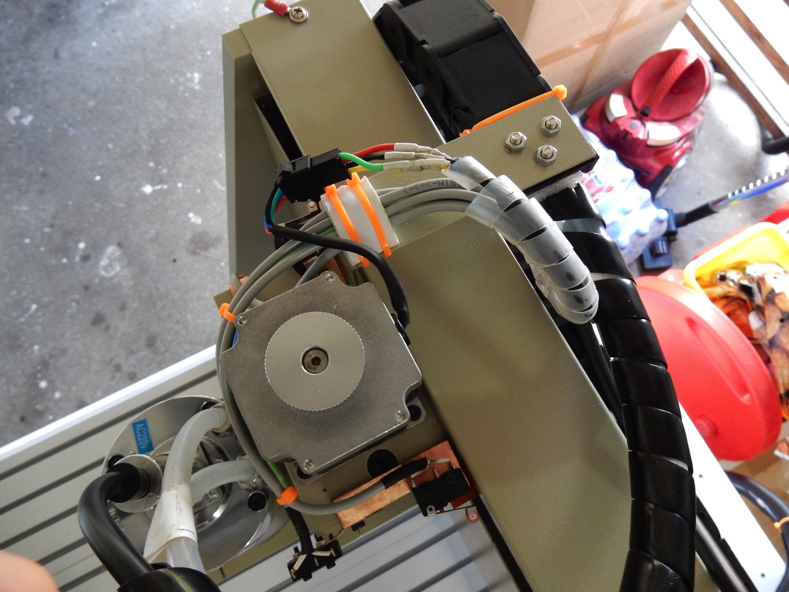
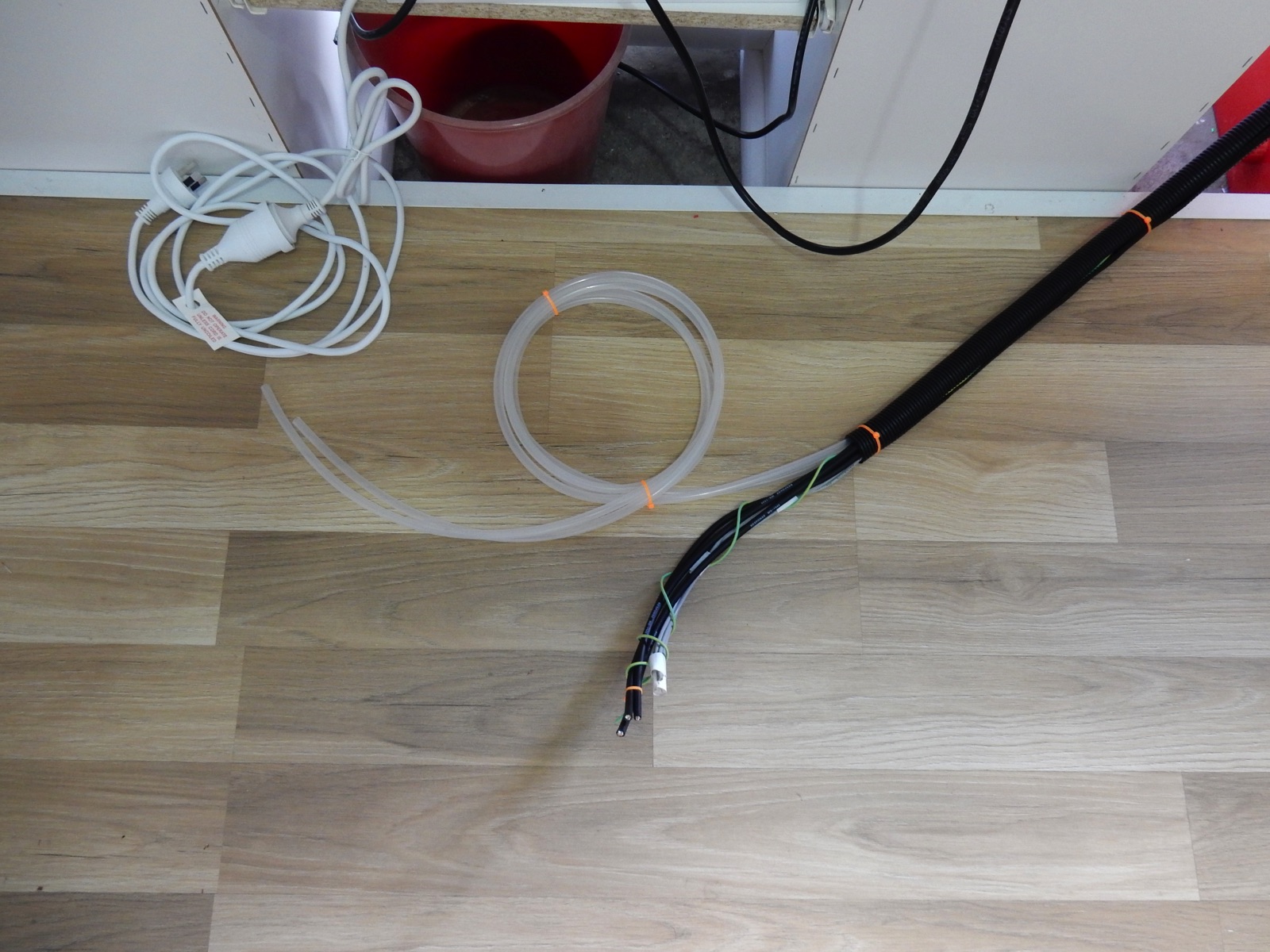
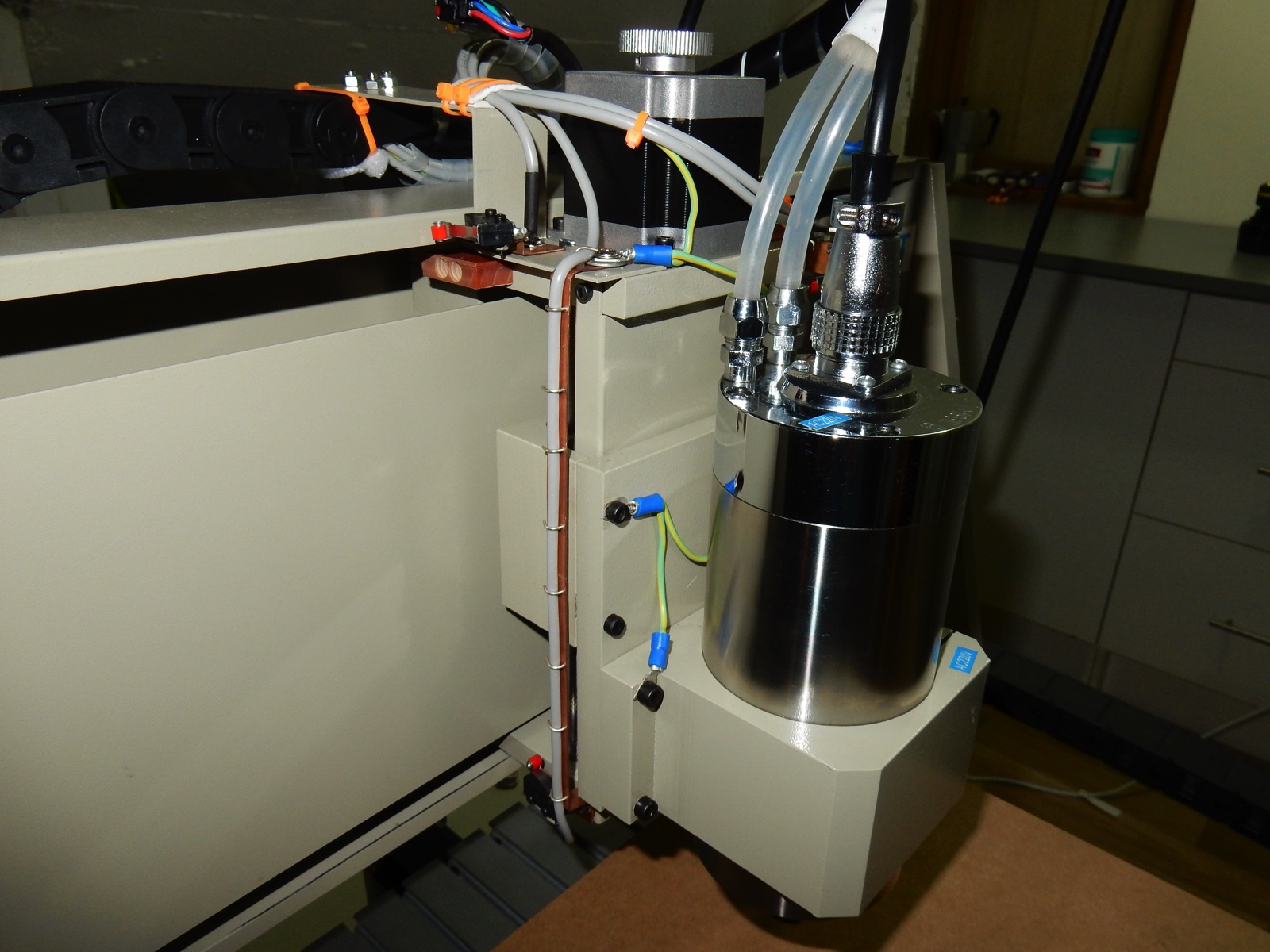
Step 3 - Installing/wiring switches and changing stepper motor cables
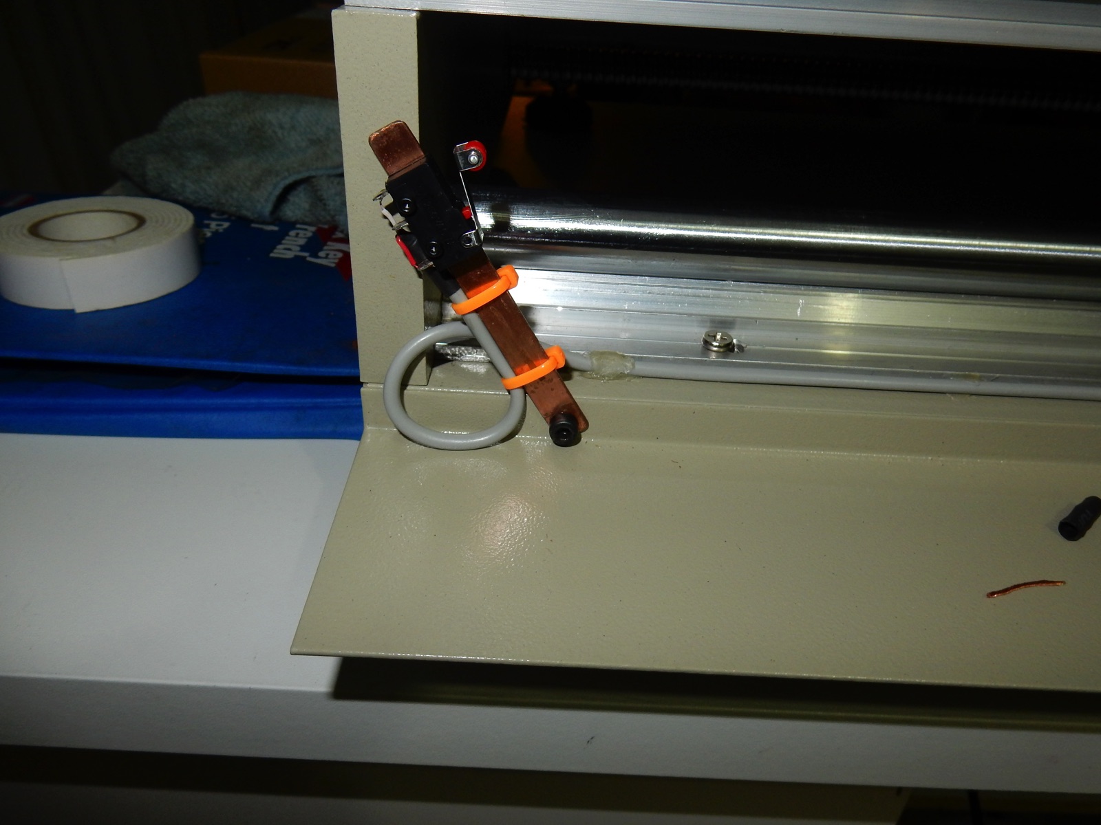
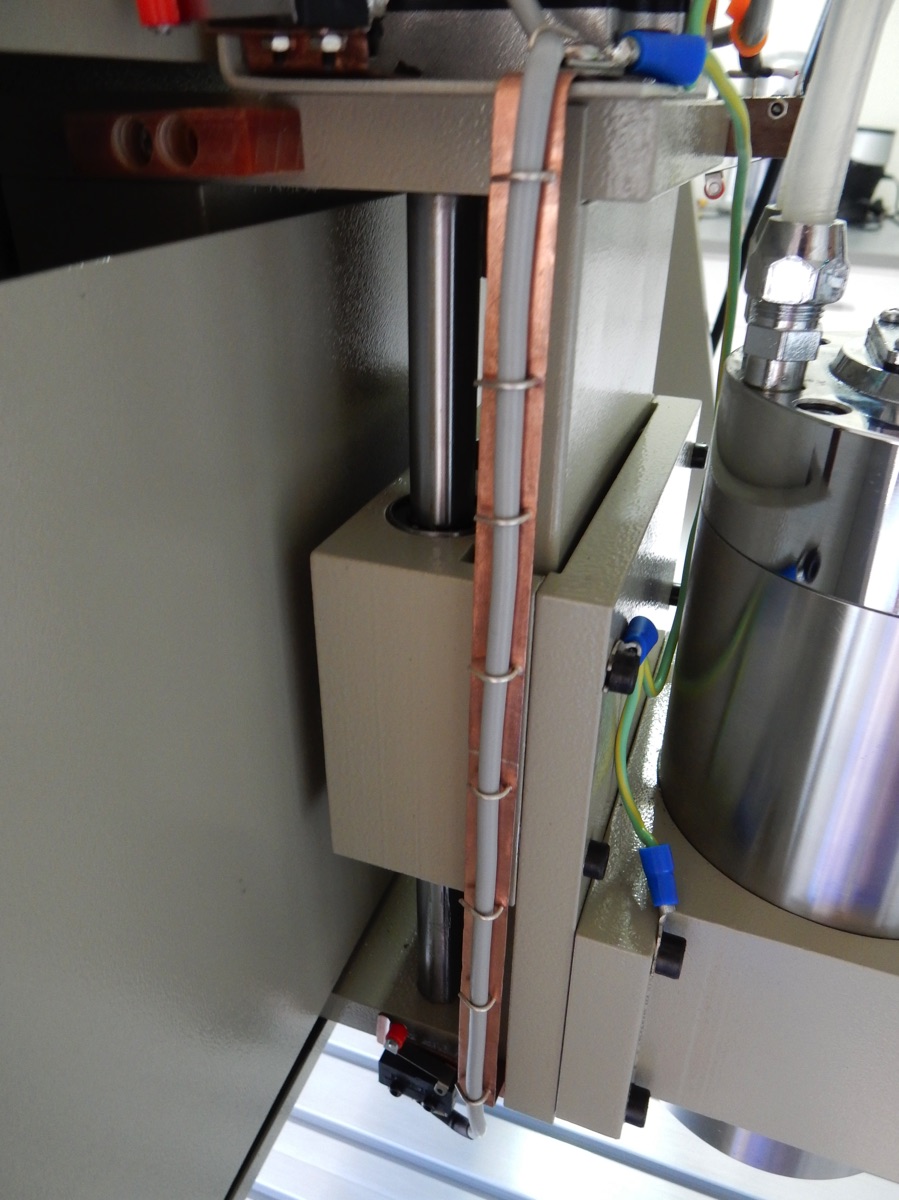
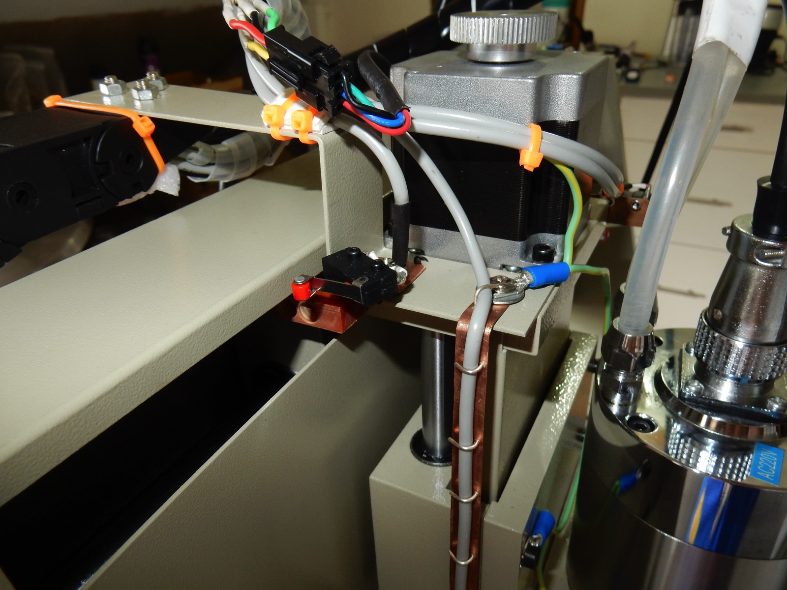
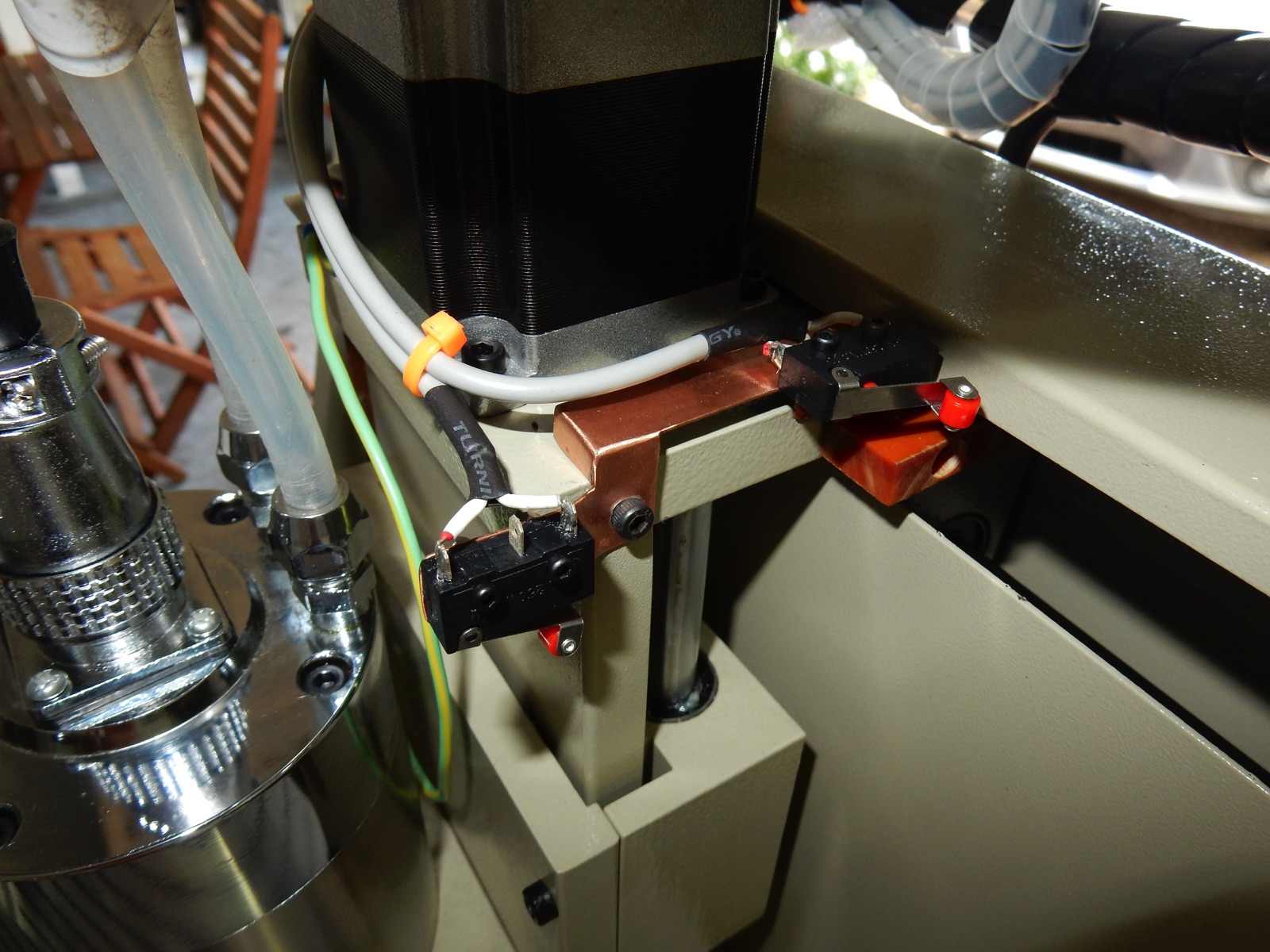
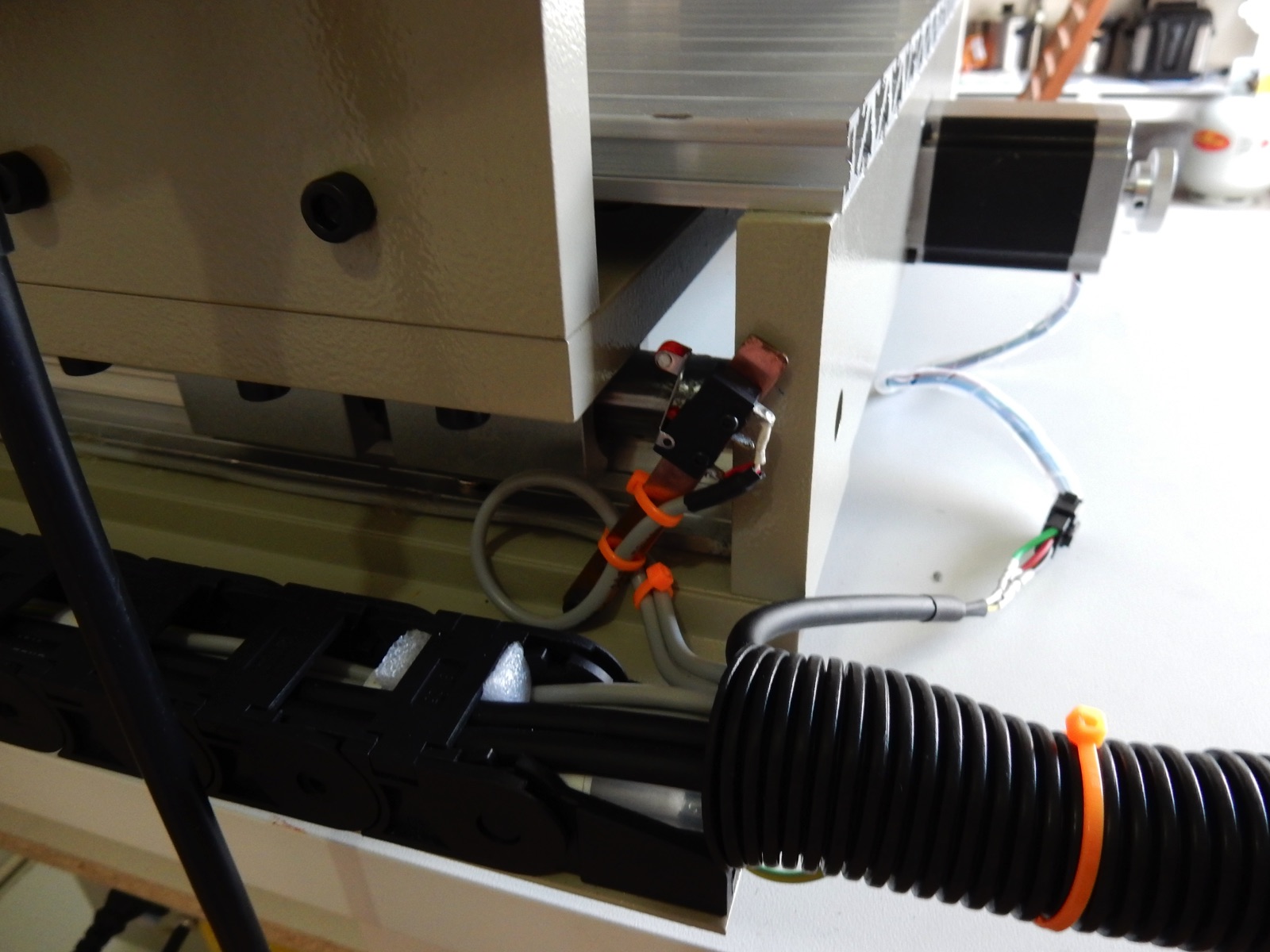
Many ways to install the switches, I just picked the easiest one for me, made a few brackets in copper to hold the switches and used existing screws to hold the brackets.
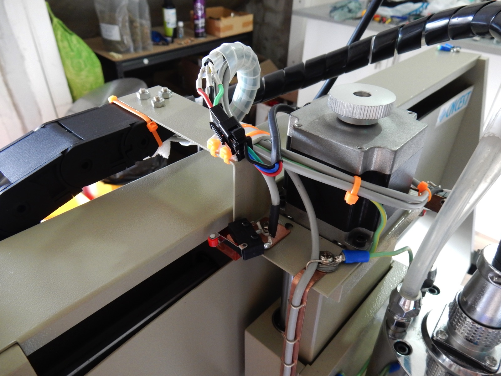
The Mach3 software can work out 'homing' and 'limits' with the switches wired in series, it saves cable, but the NVEM board I'll use has plenty of inputs so i decided to wire them individually in case I decide to use Proximity switches at a later stage i wont have to add more cables, cause it's a pain!. Switches are wired in 'NC normally closed position' with 2 core shielded cables.
For Stepper motors i used high quality flexible 4 core shielded microphone cable, it can handle 5Amps or so per core, the stepper motors are 3Amps. Cables from Jaycar.... overpriced, ripoff !
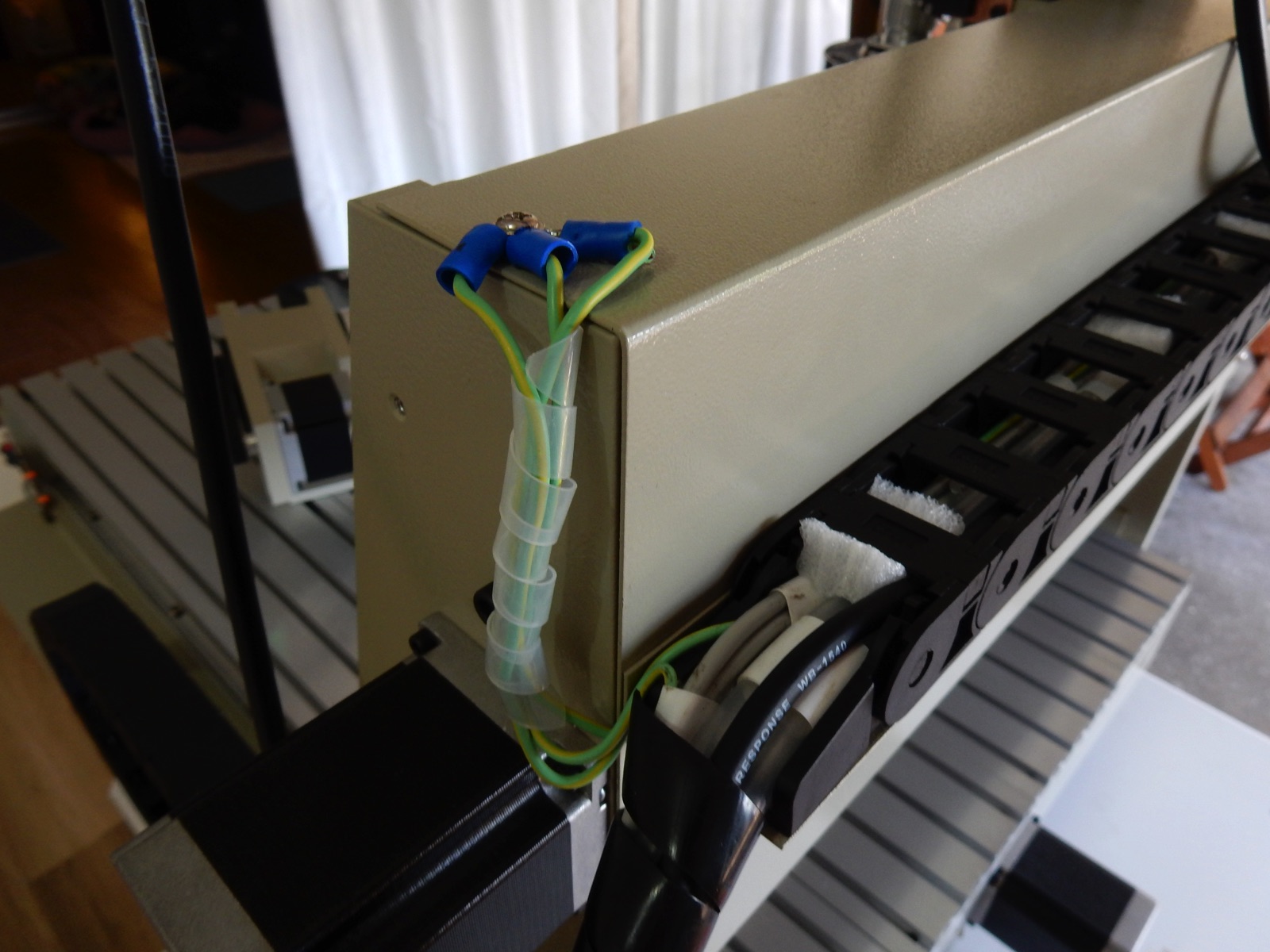
I haven't changed the Spindle cable yet, Jaycar did not have any that i could use, I just got the cable out of the rail for now so it doesn't run along the signal cables and cause possible interferences .
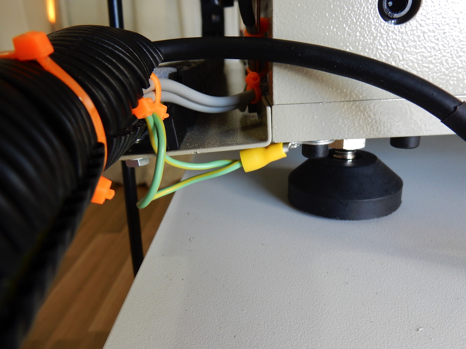
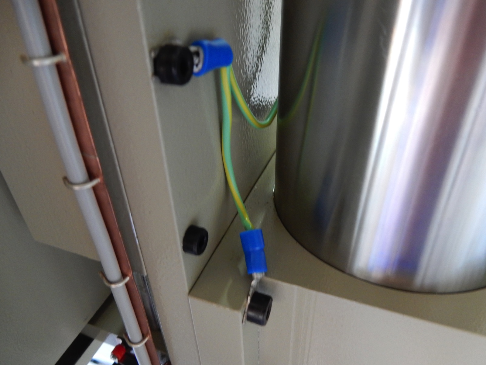
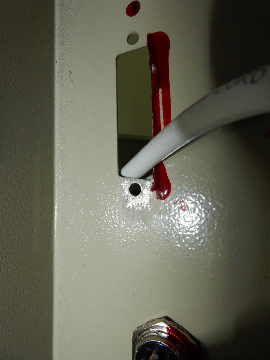
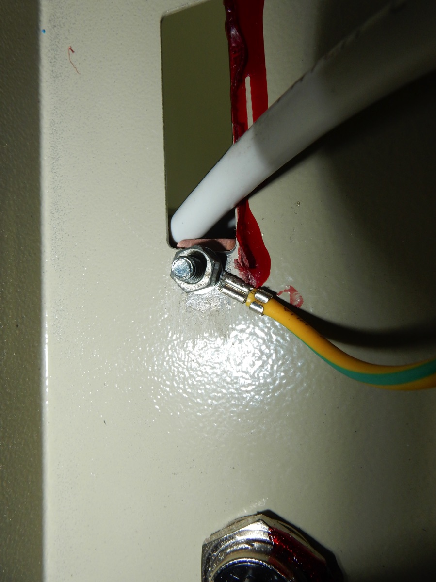
I ensured ground continuity in the frame by scratching paint under some screws and linked moving parts with cables . Never rely on ball bearings for ground continuity :-) . I then linked a main ground cable from the frame, the other end will be connected to the controller's ground, along with the cable shields and main power supply earth.
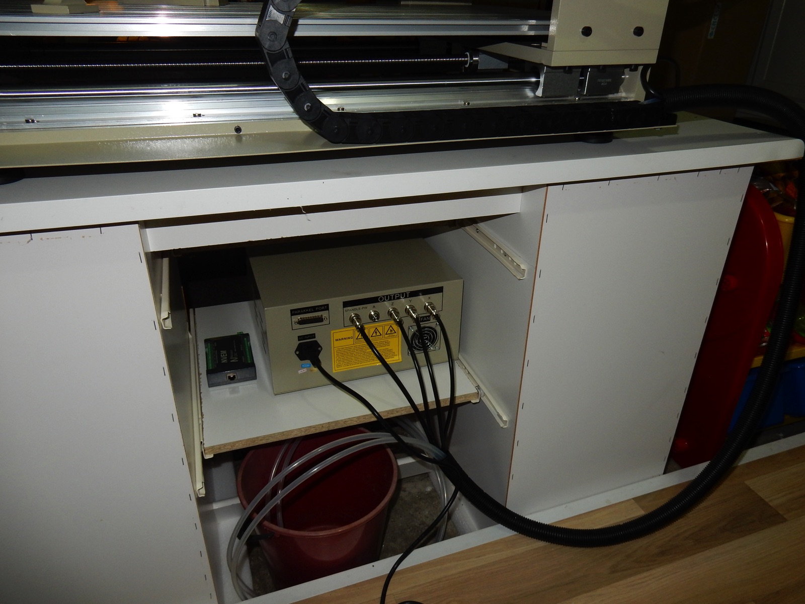
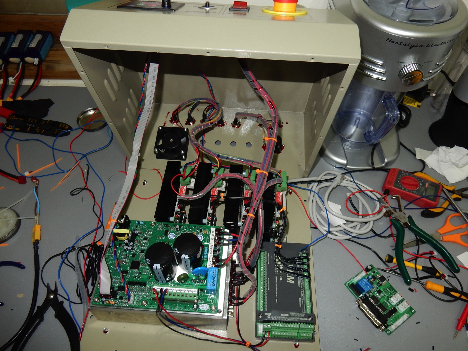
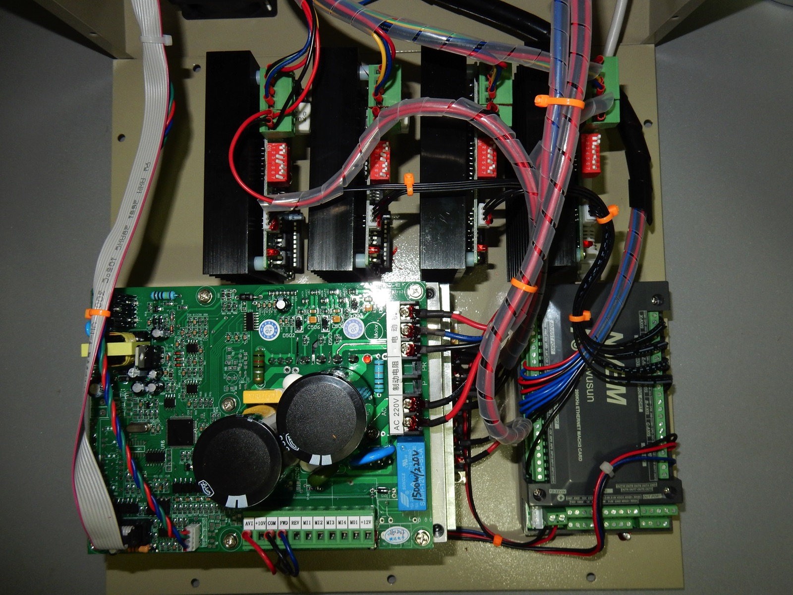
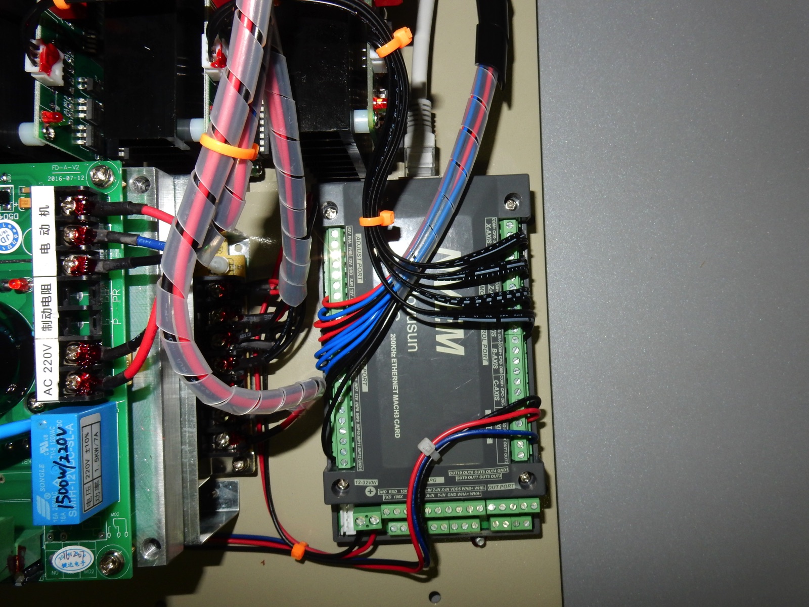
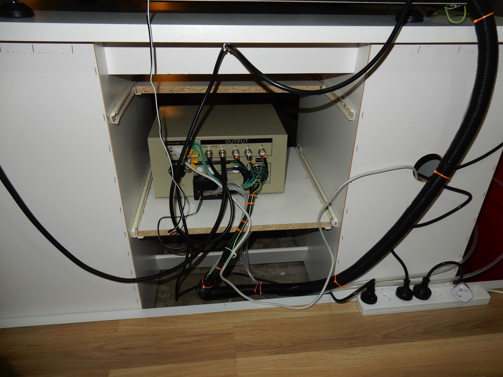
Step 4 - Replacing LPT Breakout board with NVEM Motion board
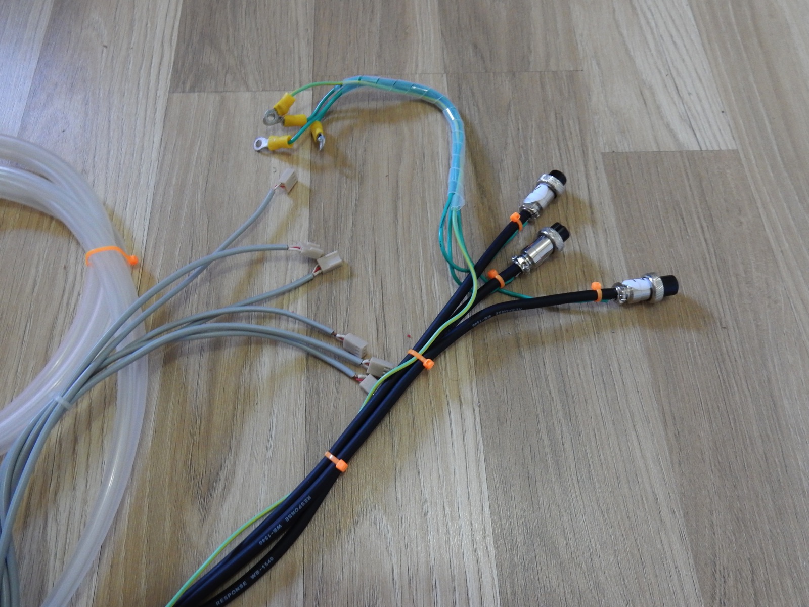
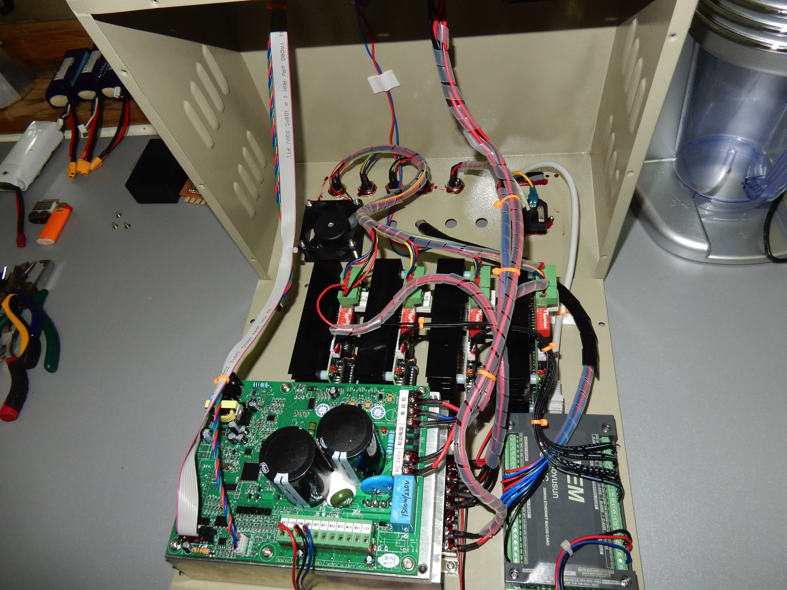
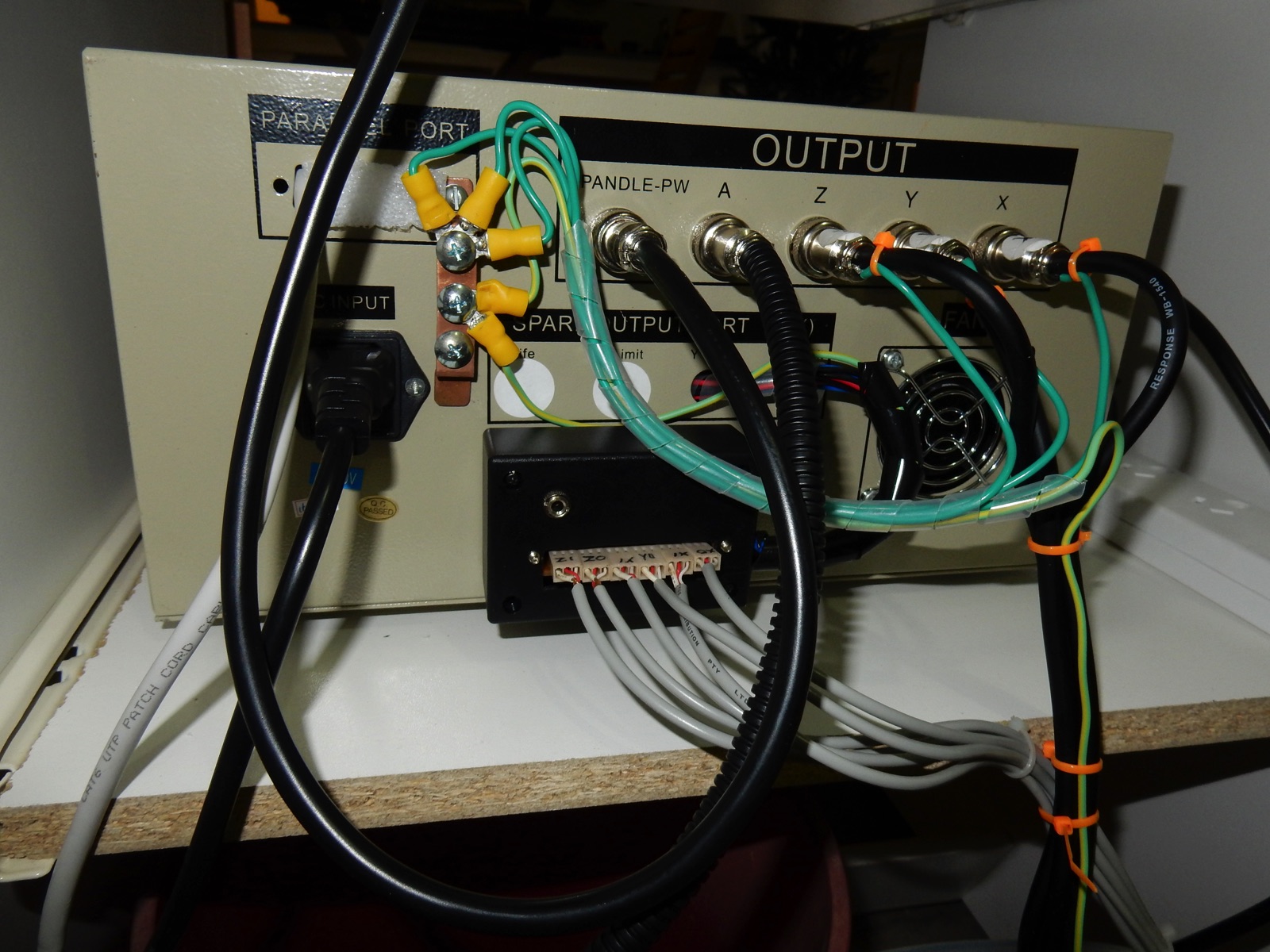
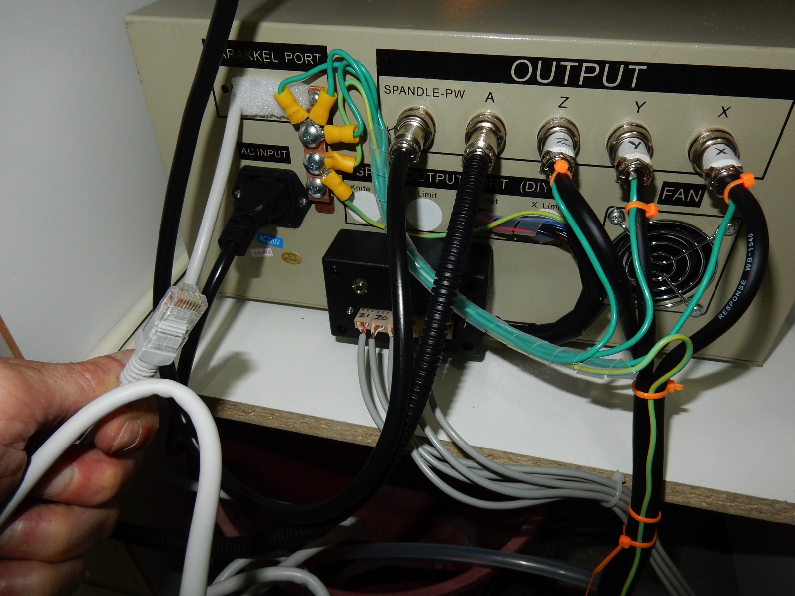
That took me a while, I found a spot just big enough in the controller! . Wired NVEM board to power supply, VFD, stepper motor drivers and E-Stop.
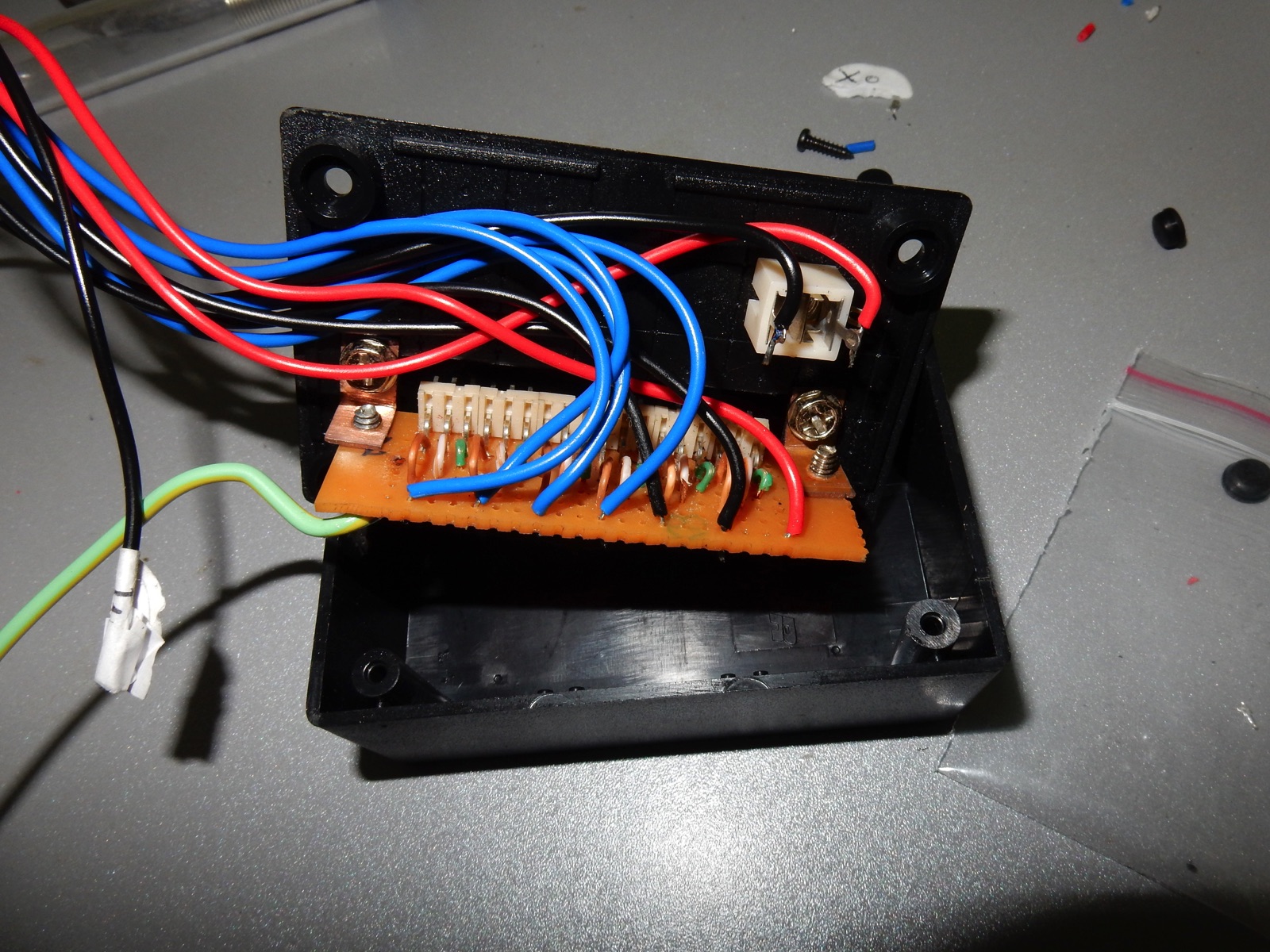
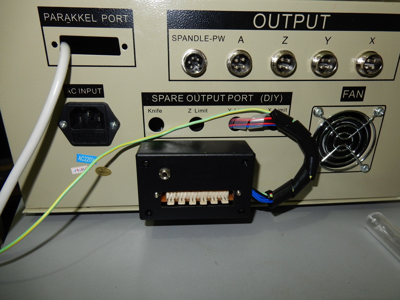
For the Home/limit switches and Z probe , the connectors I ordered never turned up and i didn't want to wait an other 3 weeks so i made a connection 'box' with a circuit board and some small connectors from Jaycar. I used a Jack plug for the Z-probe .
The home/limit switch cables are shielded so i linked all the the shielding together and to a centralized ground/earth connector that i made with a piece of copper and is itself connected to the main power earth.
I scratched the paint under some screw linking the controller metal panels and under the screws holding the Power supply, VFD, motor drivers so everything inside is grounded as it should be.
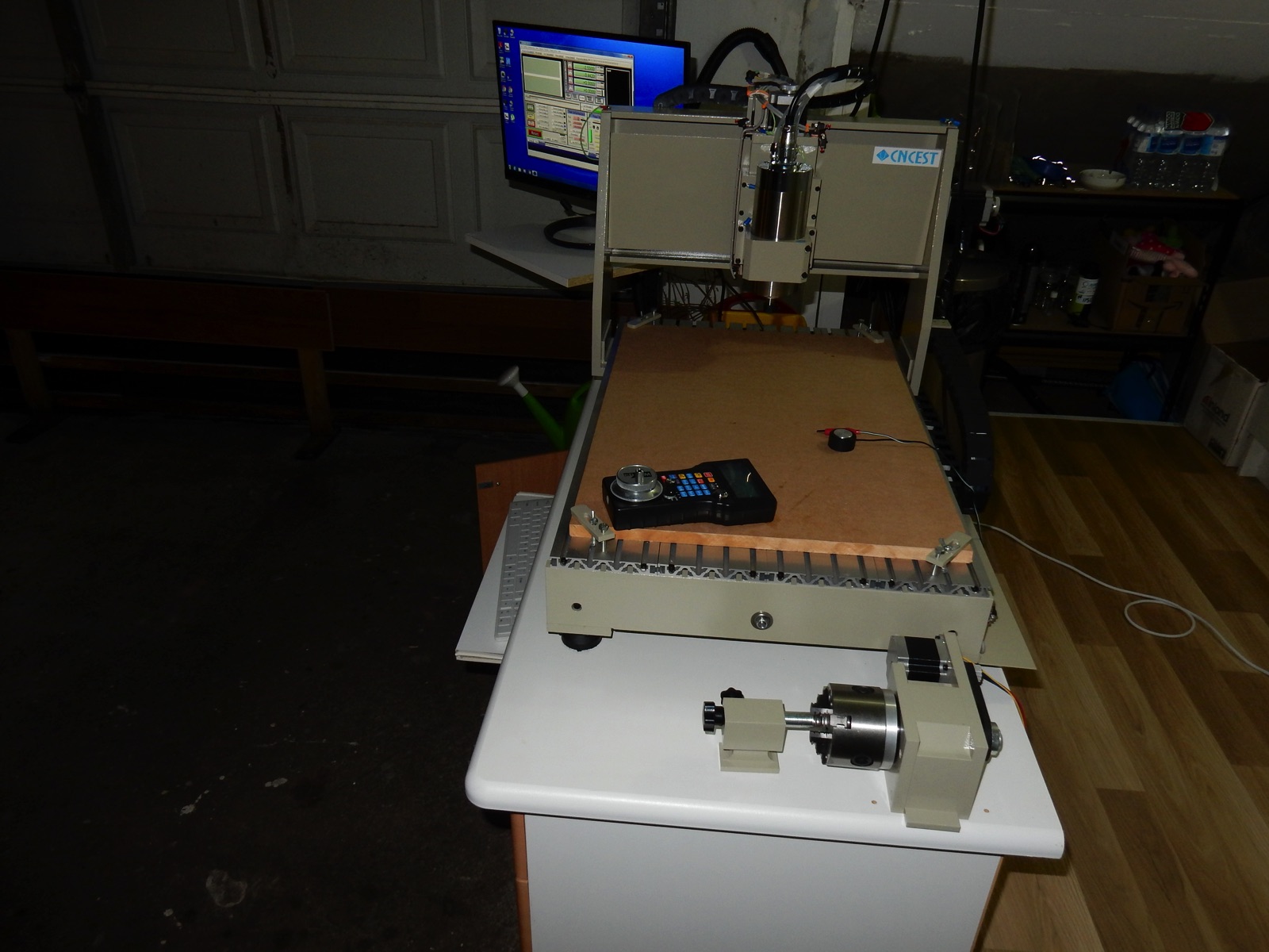
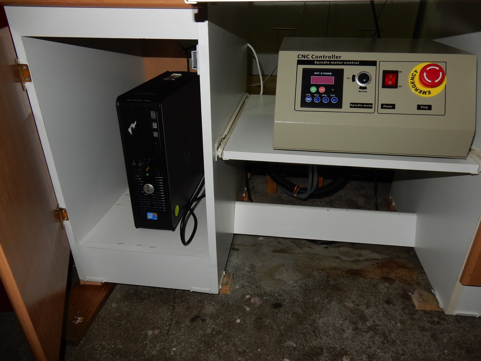
Step 5 - Adding a computer to run Mach3 and Aspire Vectrics
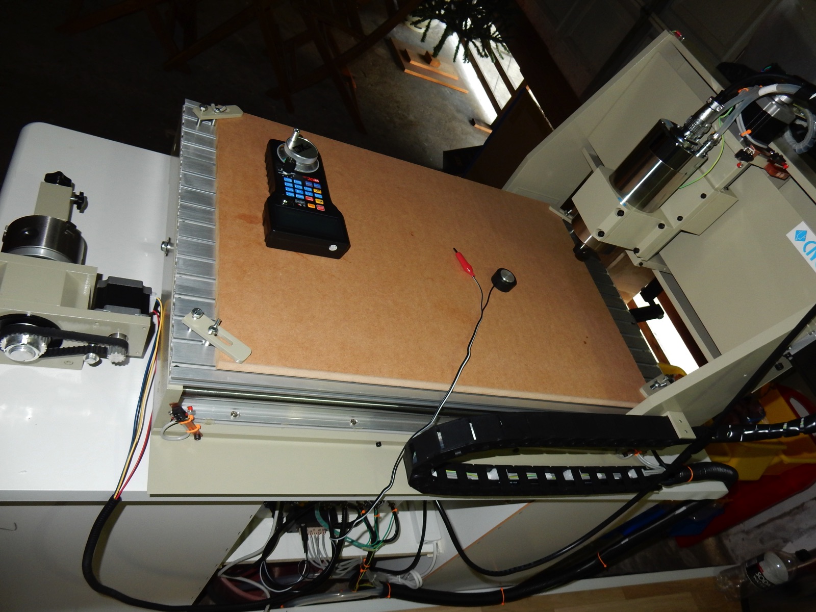
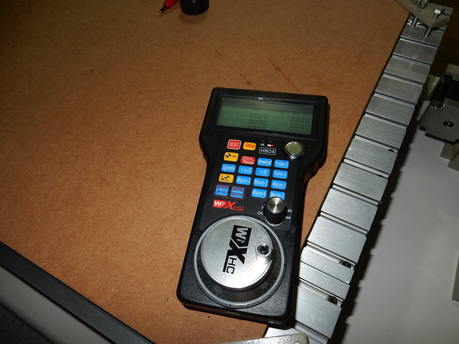
I'm over my budget now, amazing how cables and other little bits and pieces add-up !. I couldn't resist, i got a "HB04 Wireless Hand wheel MPG Pendant", i didn't really need it but it looks so kewl ;-).
For the computer, i found on Ebay, a refurbished "Dell Optiplex 780,Core 2 Duo 2.93GHz 4GDDR3 250G" with windows 7 64bit. I got it before the CNC so i made sure it had a parallel port, just in case i would have to revert to LPT. I also go a brand new "Acer - UM.VR1SA.001 - 23" " LED monitor. on special from Bing Lee.
AU$115 for the PC, AU$129 for a brand new 23" screen , Au$16 for a metal monitor mount, Bargain !! , and they work !!:-)
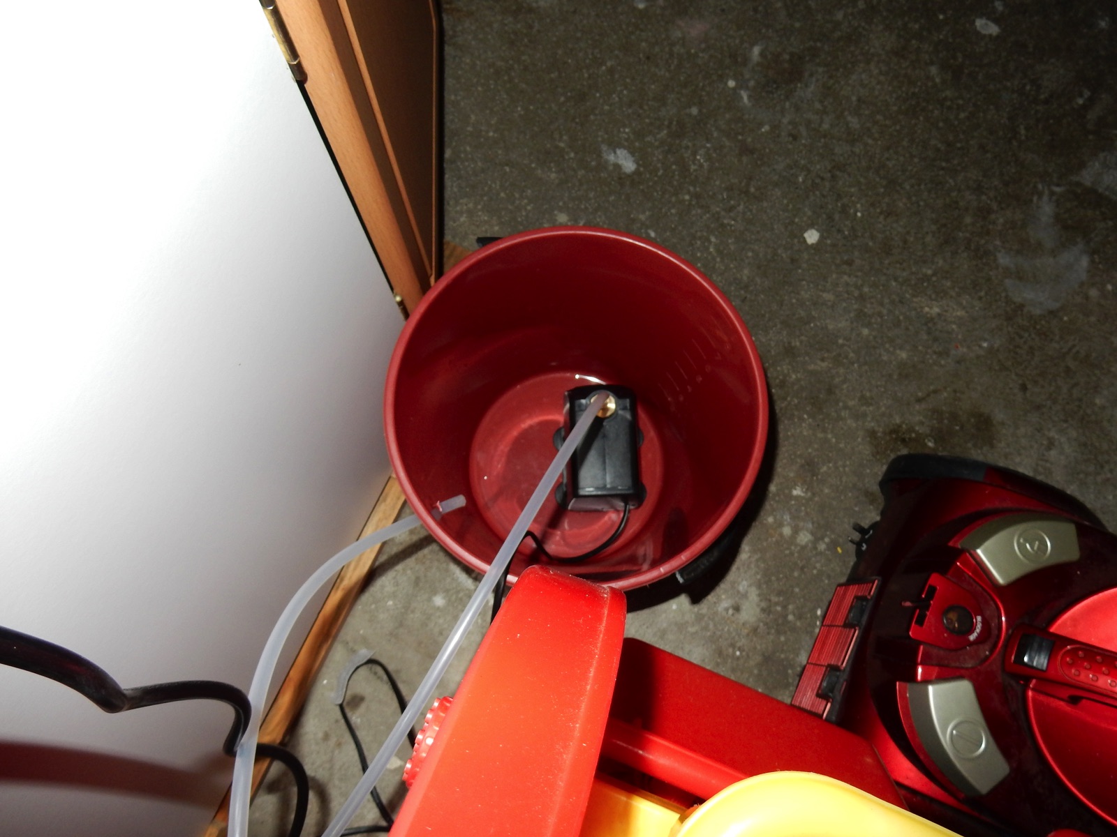
Oh yeah, i used a small bucket to put the spindle water cooling pump but I'll have to find something a bit bigger , not sure how quick the water is going to heat.
So i think that's it for the hardware side of things for now, it looks great !!!, I'm wrapped :-) and nothing took fire when i started it, but i have no idea if anything works at all yet or even if stuffed up or not with wiring and solders :-/ . I downloaded and installed Mach3, and Aspire Vectric. I think this computer wont cut it to run Vectric, but I'll worry about that later.
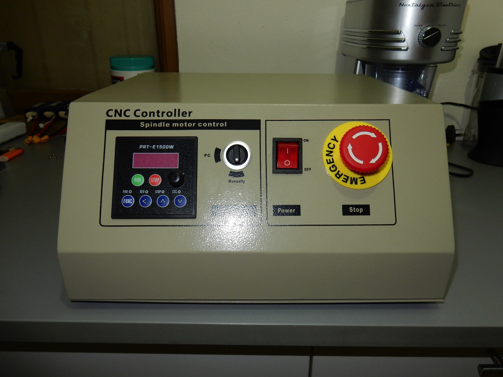
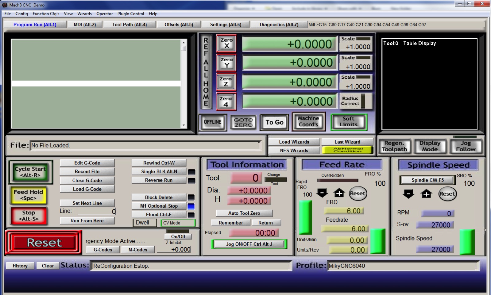
Step 6 - Setting up Mach3
OMG ! . I didn't know it was going to be that much of a pain. That's when i realised i should have kept the Controller with it's original LPT board, setup and learn mach3 then only upgrade the board .
Too many factors to consider at the same time... is the problem caused by my wiring ? maybe it's just the way Mach3 works and I'm not understanding it ? or is it a problem with the NVEM board? driver? maybe it's just me going insane ?
I lost hair in the process, but to cut the long story short, i took the time to watch all the Mach3 tutorials and more , any you-tube videos that could help me to understand how it is all supposed to work.
I first encountered major issues with switches acting erratically , ok some times, other times the axis would hit the frame and crush my switch. Connections and settings looked good , it was making no sense until... i read the little line on the Flux tin "Semi-conductive, do not use on circuit boards or clean with alcohol after soldering" . Sure enough, i cleaned with acetone the little circuit board i made for the switches cable connections and Voila ! no more erratic signals.
The second issue was to get Mach3 to control the Spindle speed. No brand or documentation for the Chinese VFD which is a pain but i eventually found the answer, one setting has tho be changed in the VFD :
1. Change D001 to 1 (data revision allowed)
2. Change D032 to 1 (1 to start from the signal terminal, 0 to start from control panel )
3. Change D001 to 0 (forbid data revision)
Then some endless issues with "Soft Limits" and "Limits Overrides" . Hours of trials and errors, i thought i was doing something wrong and going insane. It turned out the NVEM Driver is mostly usable but due to unresolved driver issues, a few features are not working as they should yet.
Someone has been kind enough to become a comunication link between myself and the Chinese Developper who is not able to be contacted directly due to Internet censorship.
It is was long process but some issues have been fixed and hopefully the remaining problems will be looked at one day:
- Soft limits issues ( No news from developper since 23/05/2017)
They only work correctly when the Mach3 "Machine Coords" button is selected (Red) .
Otherwise they attach themselves to Work Coordinates when the DRO is in work coordinates mode. Soft Limits should always work in machine coordinates, even when the DRO is set to work coordinates mode. So it is a bit annoying but usable if required.
- Soft Limit Slow Zones not working ( No news from developper since 23/05/2017)
- Hitting Soft Limits cause the Axis to stop working completely, Mach3 to crash on exit, most of the time requiring power cycling the NVEM. (Resolved in driver update 23/05/2017 see below for download link)
- 'Limits Override" not working (Resolved in driver update 23/05/2017 see below for download link)
- Cant use a switch as both home and Limit , Homing is still possible by setting the switches as "Home" only , (Resolved in driver update 23/05/2017 see below for download link)
- Problem with slave axis control , Slaved axis doesnt work when jogging or homing.
Other than the above, the rest seems to work as it should for me. Clean pulse, no missed steps, smooth fast and cool stepper motor, even after extended use. I actually think the hardware is really good. I'm not giving up on it , i can still do what i need with it and with a bit of luck , the remaining driver issues will get fixed.
For more info , bug reports and be notified of Driver updates , keep an eye on this thread
Documentation can be downloaded Here
The latest Beta NVEM Driver _P (Released 23/05/2017) - can be downloaded Here
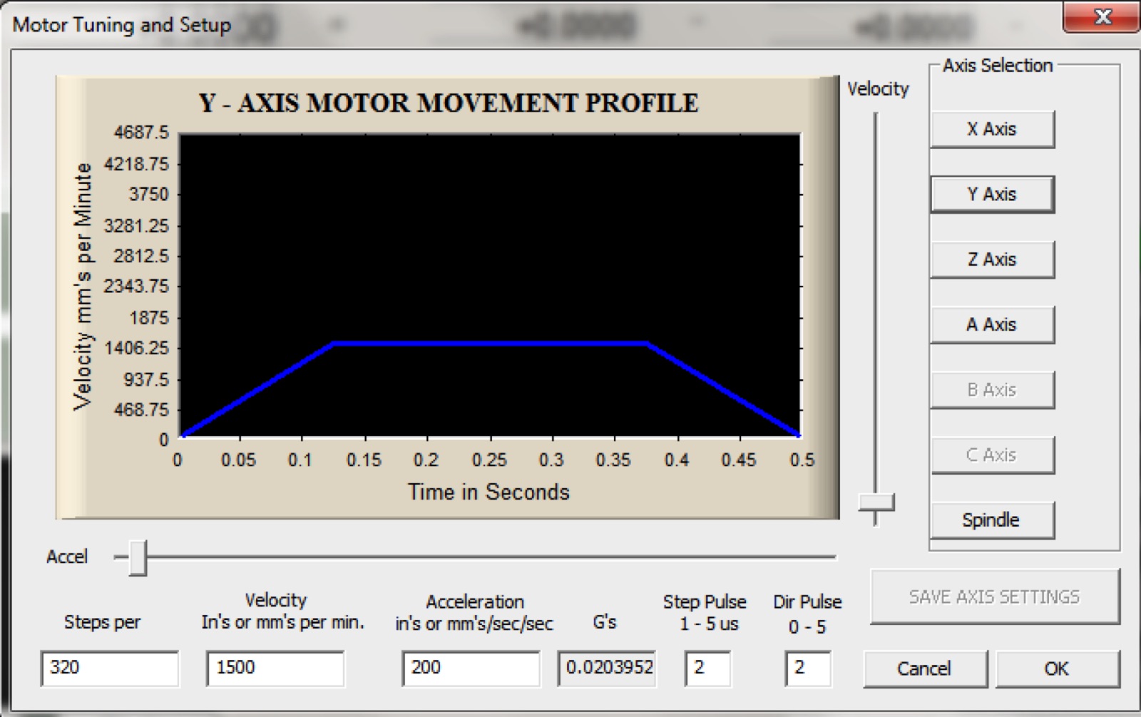
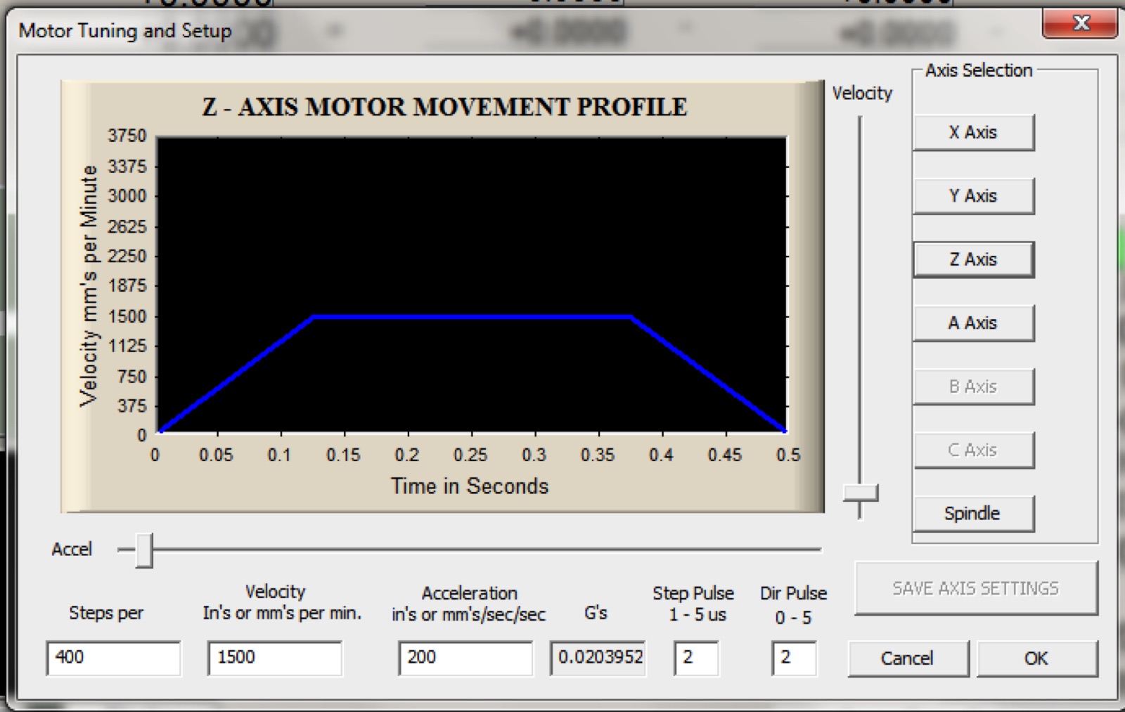
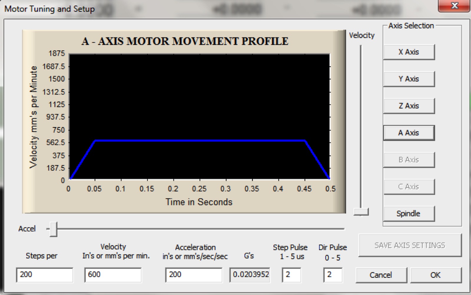
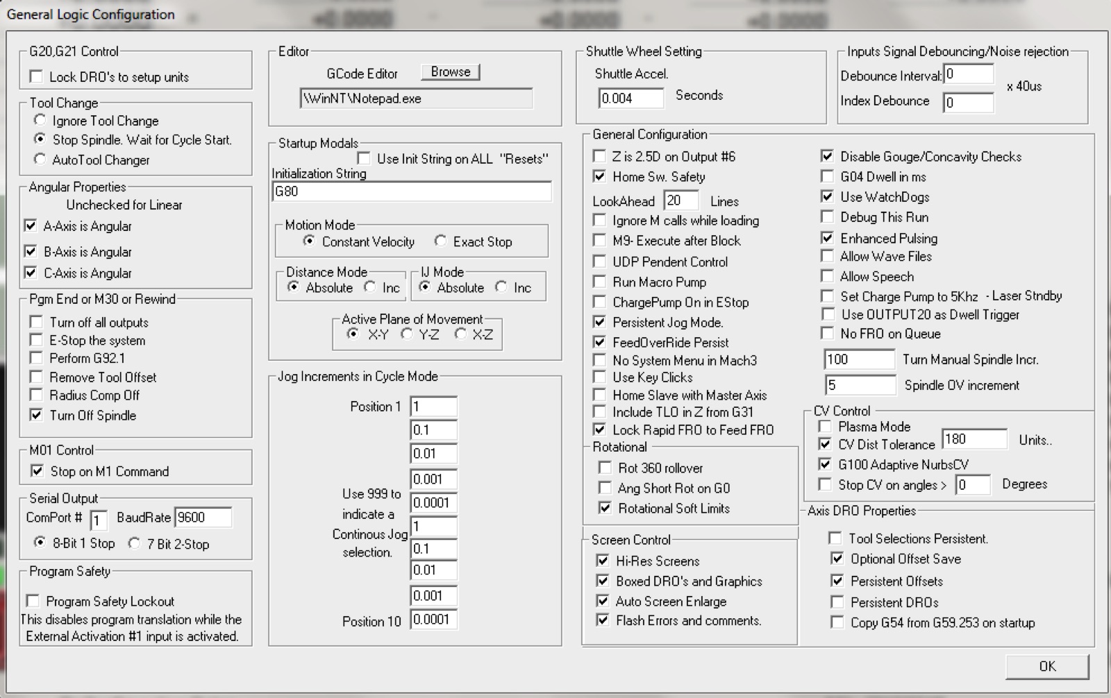
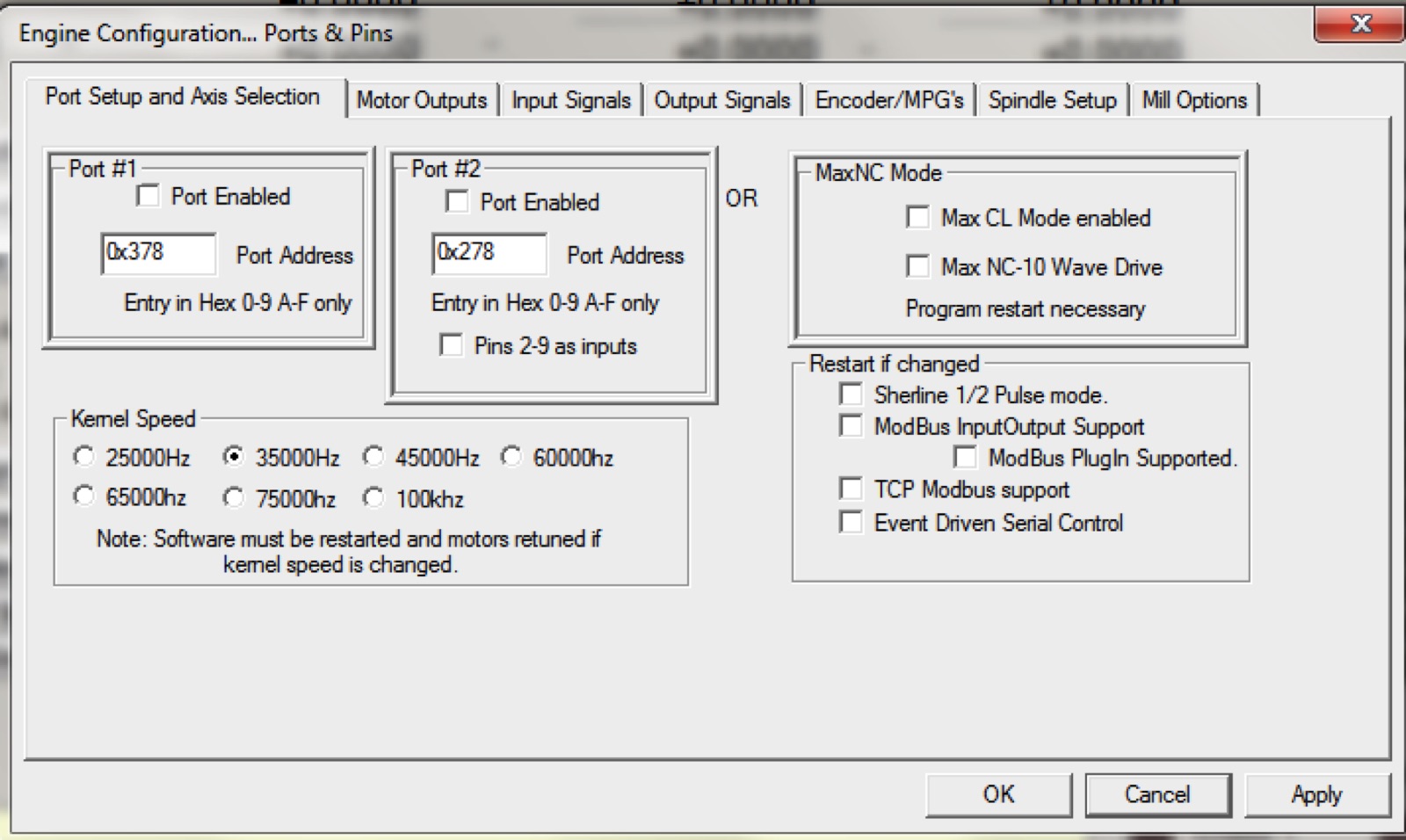
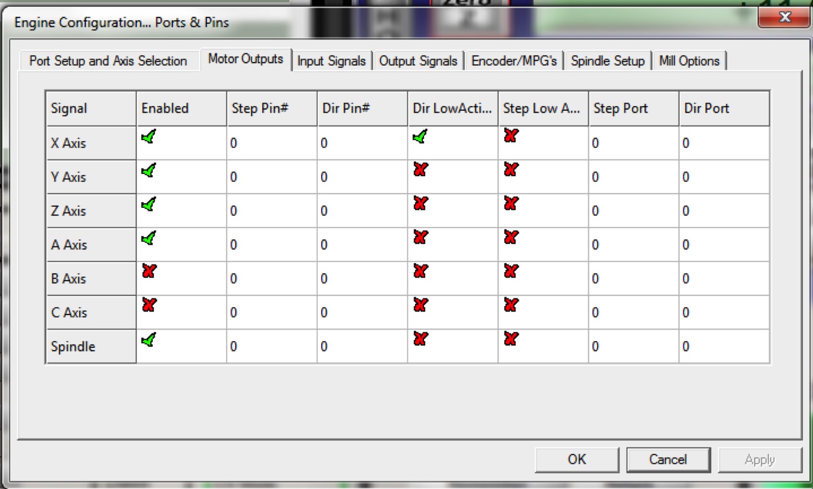
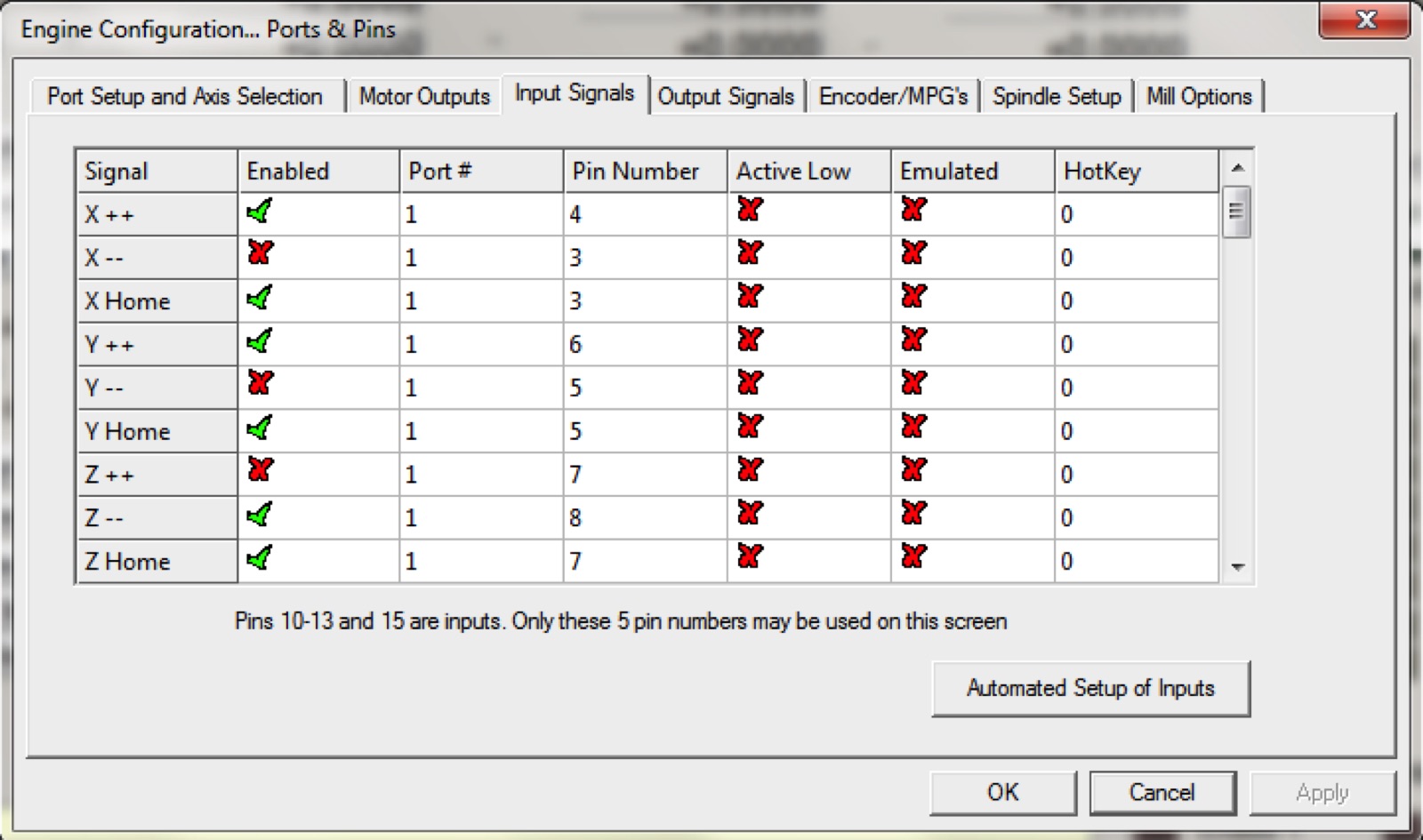
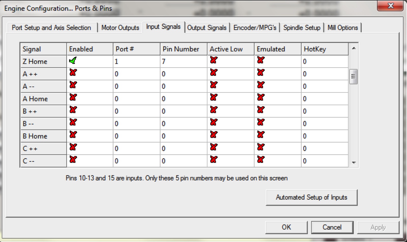
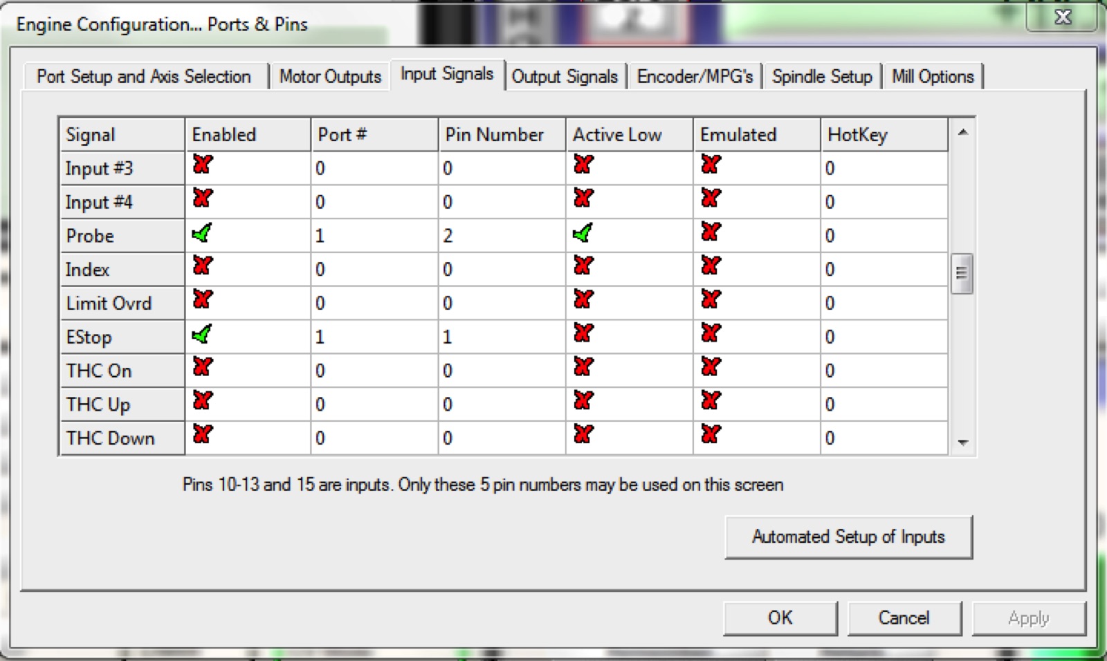
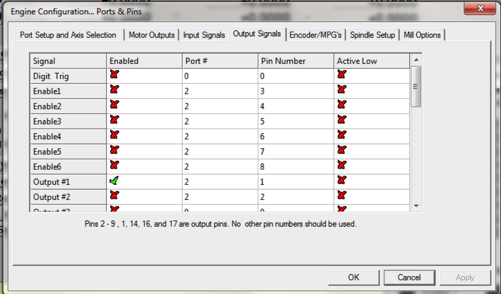
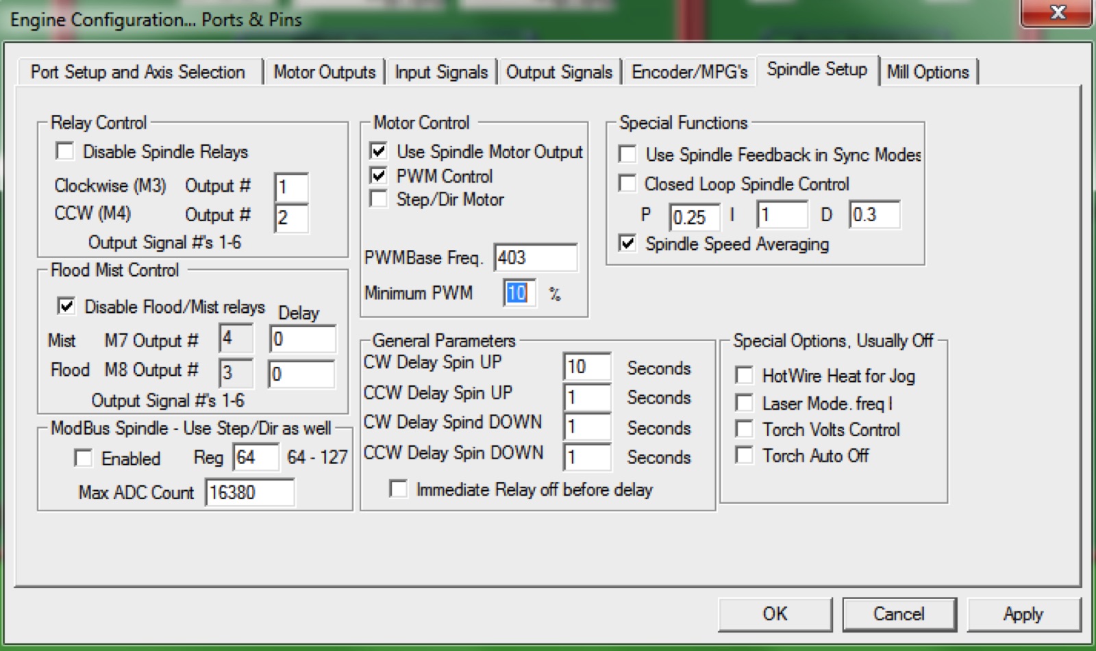
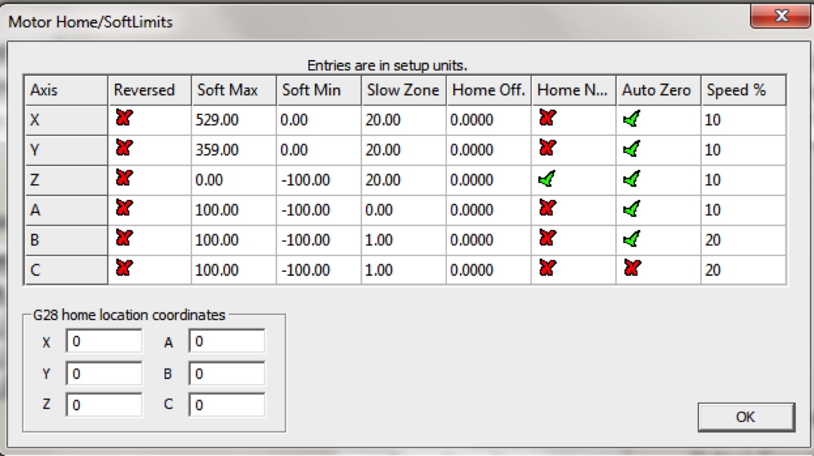
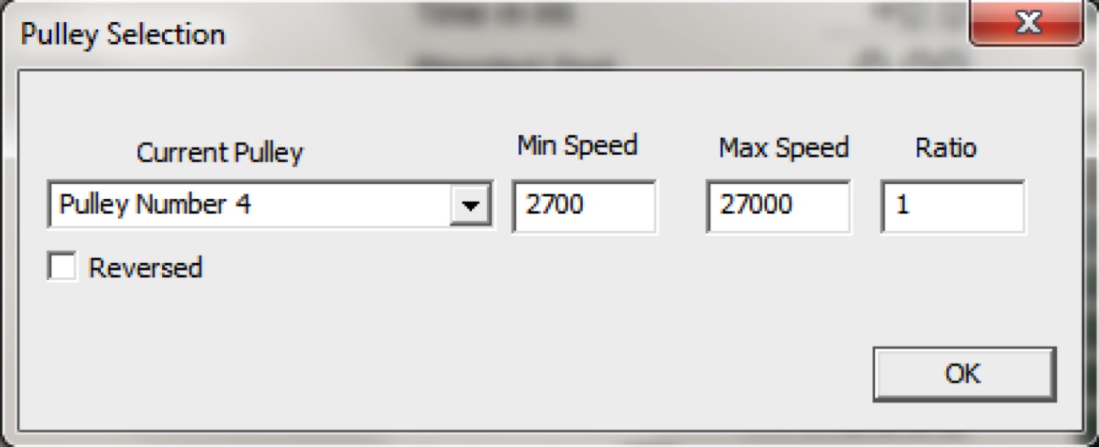
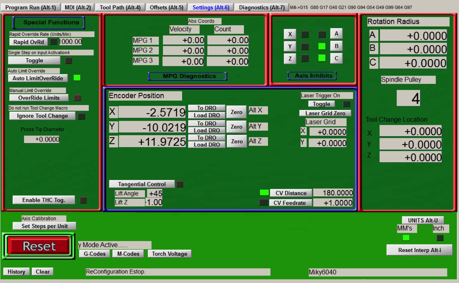
In the below gallery are my current Mach3 settings.

My Z-Probe Zero script
It works for me. Units are Metric, my probe hight is 19.3mm.
CurrentAbsInc = GetOemLED (48) 'Copy current G90/G91 state
CurrentGMode = GetOemDRO (819) 'Copy current G0/G1 state
CurrentFeed = GetOemDRO (818) 'Copy current feedrate
Contact = 0 'Clear the contact flag
PlateThickness = 19.30 'Touch Plate thickness is set here
ProbeFeed = 100 'Probing feedrate is set here
SetVar (1, -20) 'Maximum probing distance is set here
SetVar (2, 30) 'Retract height is set here
Code "M5" 'Ensures spindle is not running
Code "G21" 'Ensure metric units are used
Zs = GetOemDRO (61) 'Copy current Z-Scale DRO
Call SetOemDRO (61,1) 'Set Z-Scale DRO to 1
Label1: 'Entry point for Retry
DoOemButton (1010) 'Zero Z-Axis DRO
Code "(Setting Tool Zero)" 'Message for status bar
While IsMoving () 'Wait until task has been completed
Wend
If GetOemLED (825) = 0 Then 'Check to see if touch plate is already grounded
Code "G90 G31 Z #1 F" & ProbeFeed 'Probing move
While IsMoving () 'Wait until task has been completed
Wend
If GetOemLED (825) = True Then 'Check to see if probe has touched plate
Contact = 1 'Set the contact flag
End If
ProbePos = GetVar (2002) 'Exact point probe touched
Call SetDRO (2,PlateThickness) 'Set Z-Axis DRO to Touch Plate thickness
Code "G0 Z #2" 'Retract off Touch Plate the set distance
While IsMoving () 'Wait until task has been completed
Wend
Code "(Z-Axis is now Zeroed.)" 'Message for status bar
Code "F" & CurrentFeed 'Restore feedrate to original setting
If Contact = 0 Then 'Probe reached max travel without touching
Code "(ERROR - Probe did not touch.)" 'Message for status bar
Response = MsgBox ("ERROR - Probe did not touch.",37,"Auto Tool Zero")
If (Response = 4) Then 'User chose Retry
GoTo Label1 'Retry Probing routine
End If
End If
Else
Code "(ERROR - Touch Plate is grounded.)" 'Message for status bar
Response = MsgBox ("ERROR - Touch Plate is grounded - Check connection.",16,"Auto Tool Zero")
End If
Call SetOemDRO (61,Zs) 'Restore Z-Scale DRO to original setting
If CurrentAbsInc = 0 Then 'If G91 was in effect before then return to it
Code "G91"
End If
If CurrentGMode = 0 Then 'If G0 was in effect before then return to it
Code "G0"
End If
First attempt at using the CNC (27/02/2017)
It will take a while to learn Vectrics (to start) and a lot of trials and errors. I have the feeling using the 4th axis is going to be a big challenge and will have to wait for a while. It's my 2017 project so hopefully i should be able to do most things by 2018 :-). I also worked out that Aspire Vectrics is great and will be adapted to many things it'd like to do but i also need something a bit more 'industrial' orientated so i started to also learn Fusion 360 which i'm getting to like very much as well. So much to try , so much to learn , so little time :-)
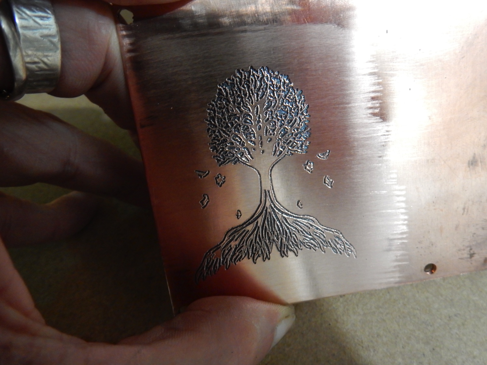
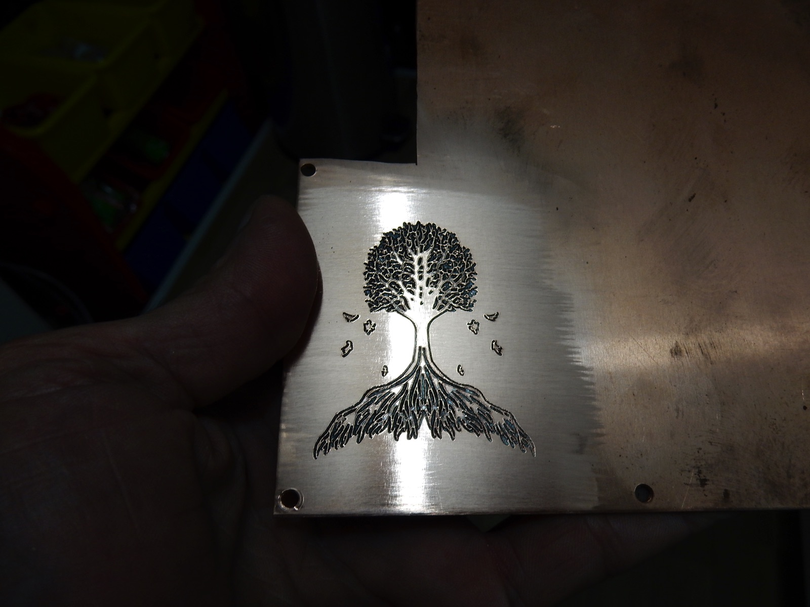
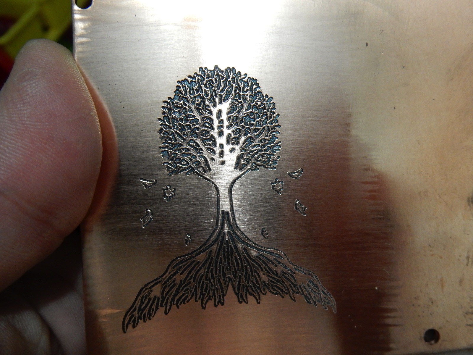
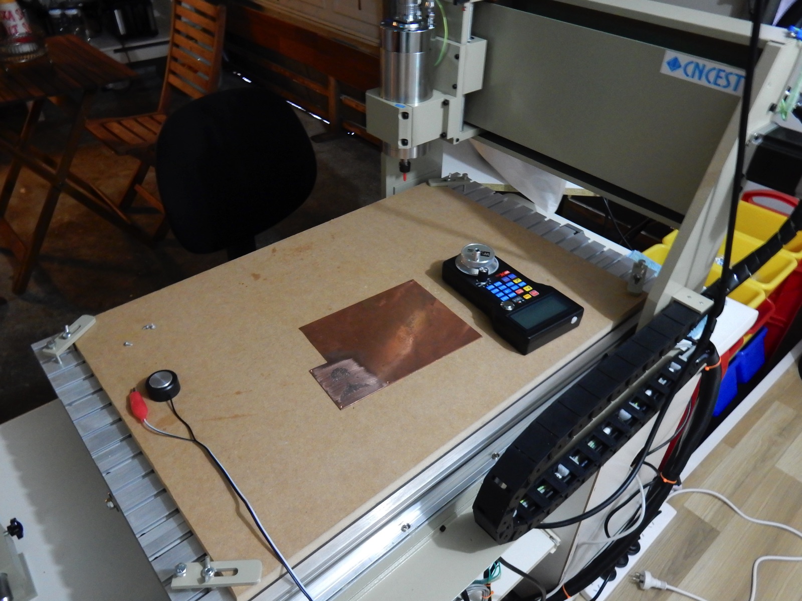
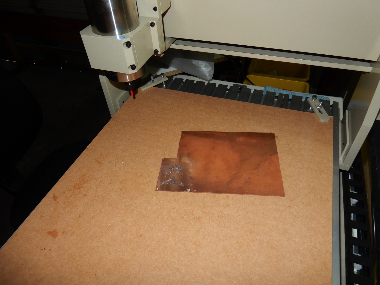
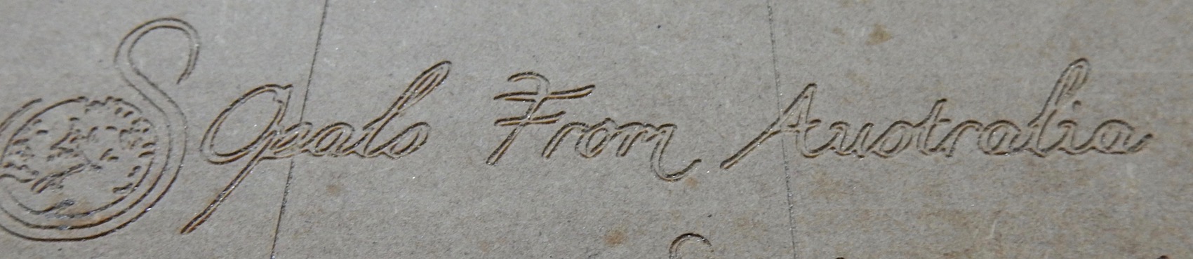
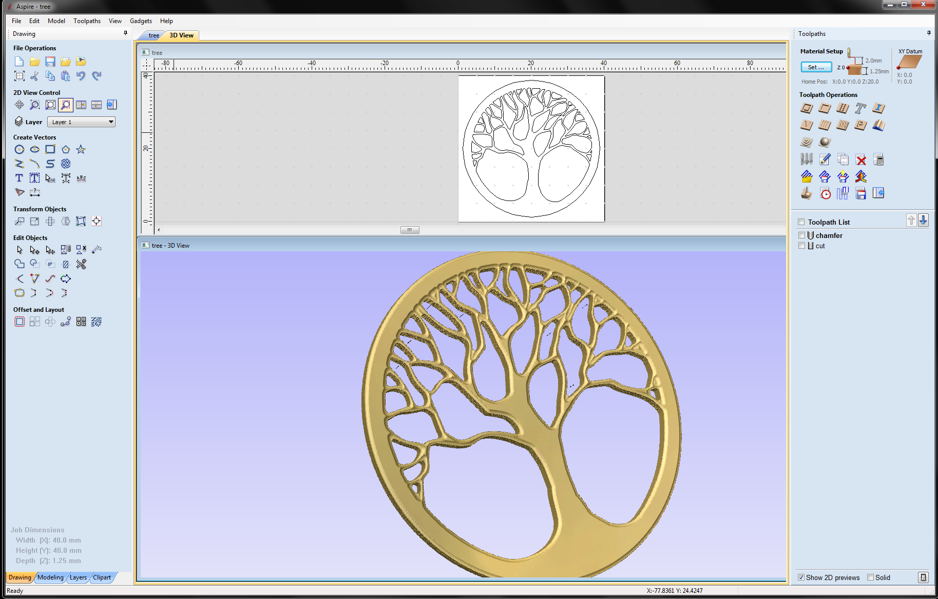
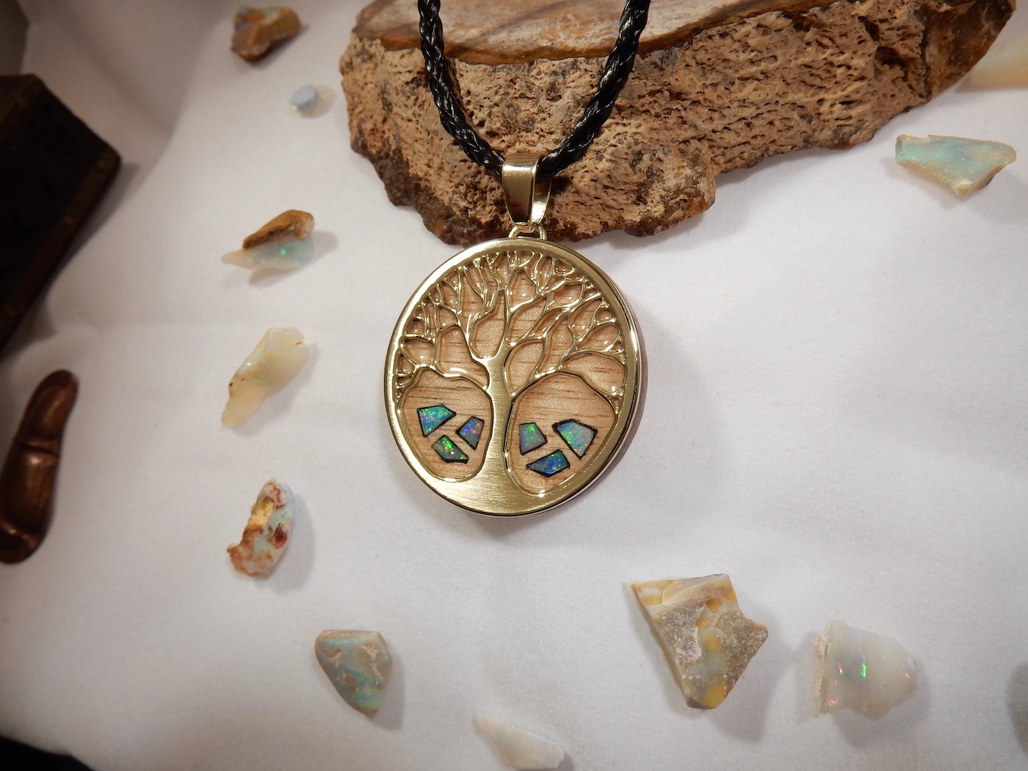
I have to start somewhere. I only have a couple of cutting/milling bits , the rest have not arrived yet so I'm limited for a while. I have a 0.2mm 30degree engraving bit so I downloaded a 'tree' model and used Vectrics to generate the Gcode to engrave it on a plate of 1.2mm copper i had handy.
I'm very happy with it :-) and it's just an engraving test ! a new world to explore now :-)
I should inlay the copper tree in a wooden box now, that would be something good to try next.
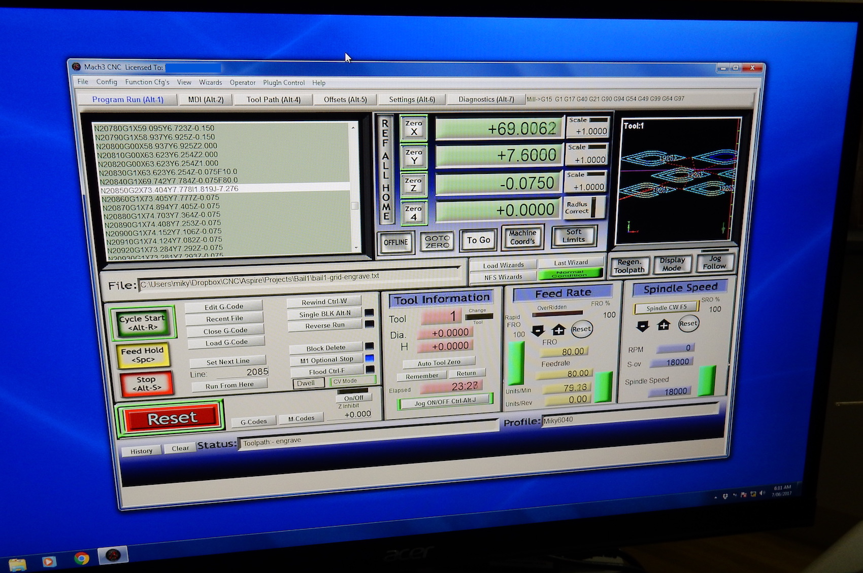
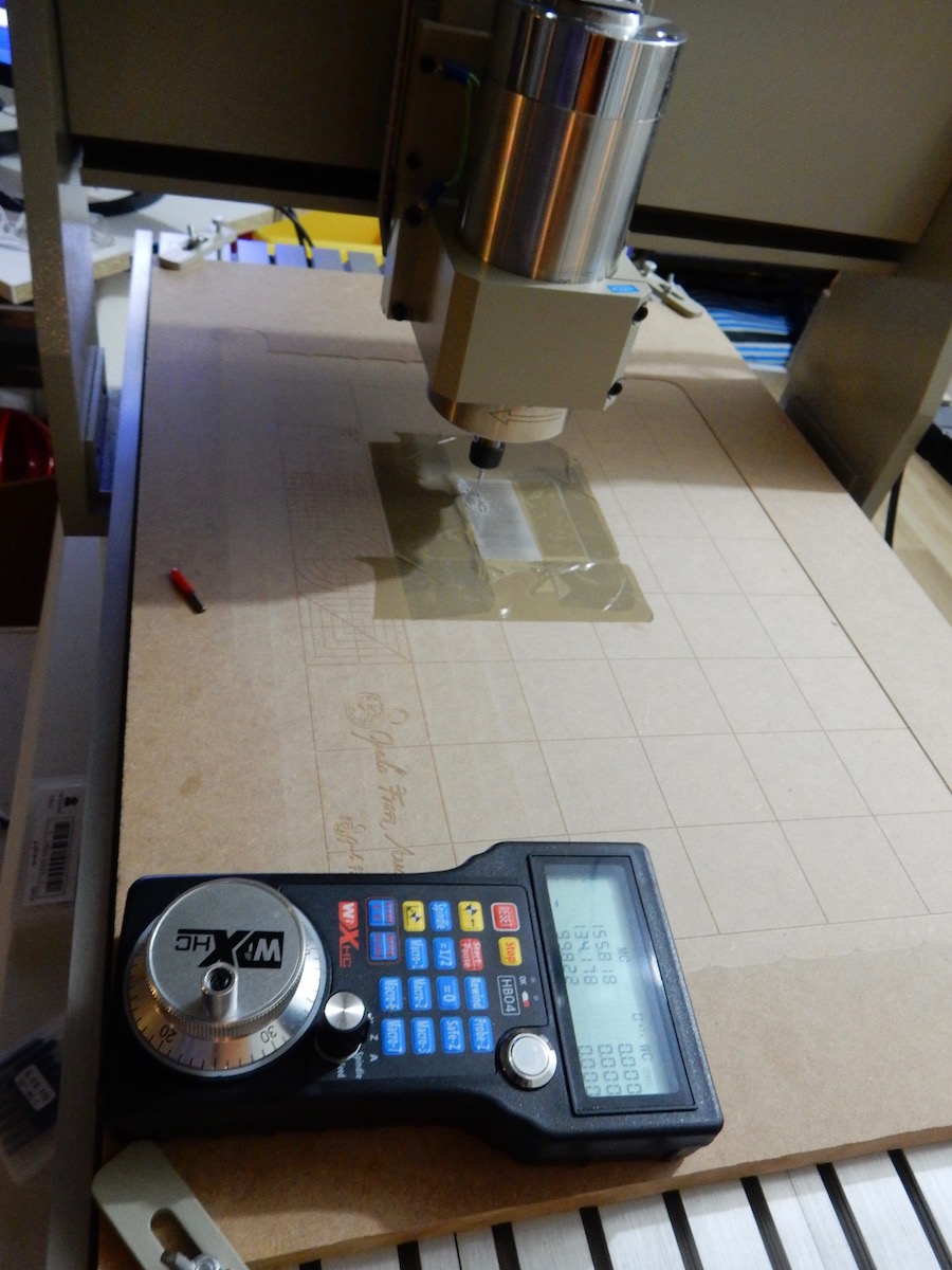
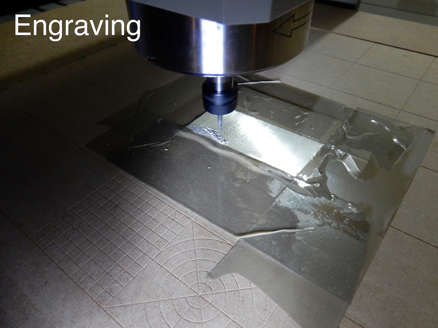
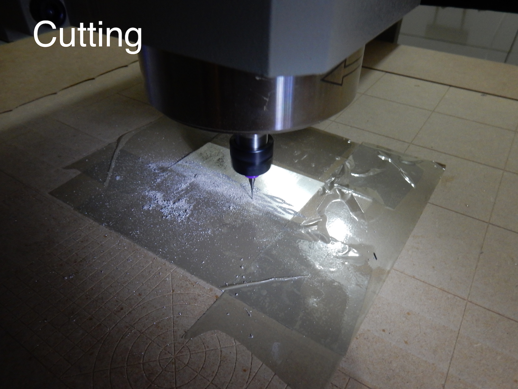
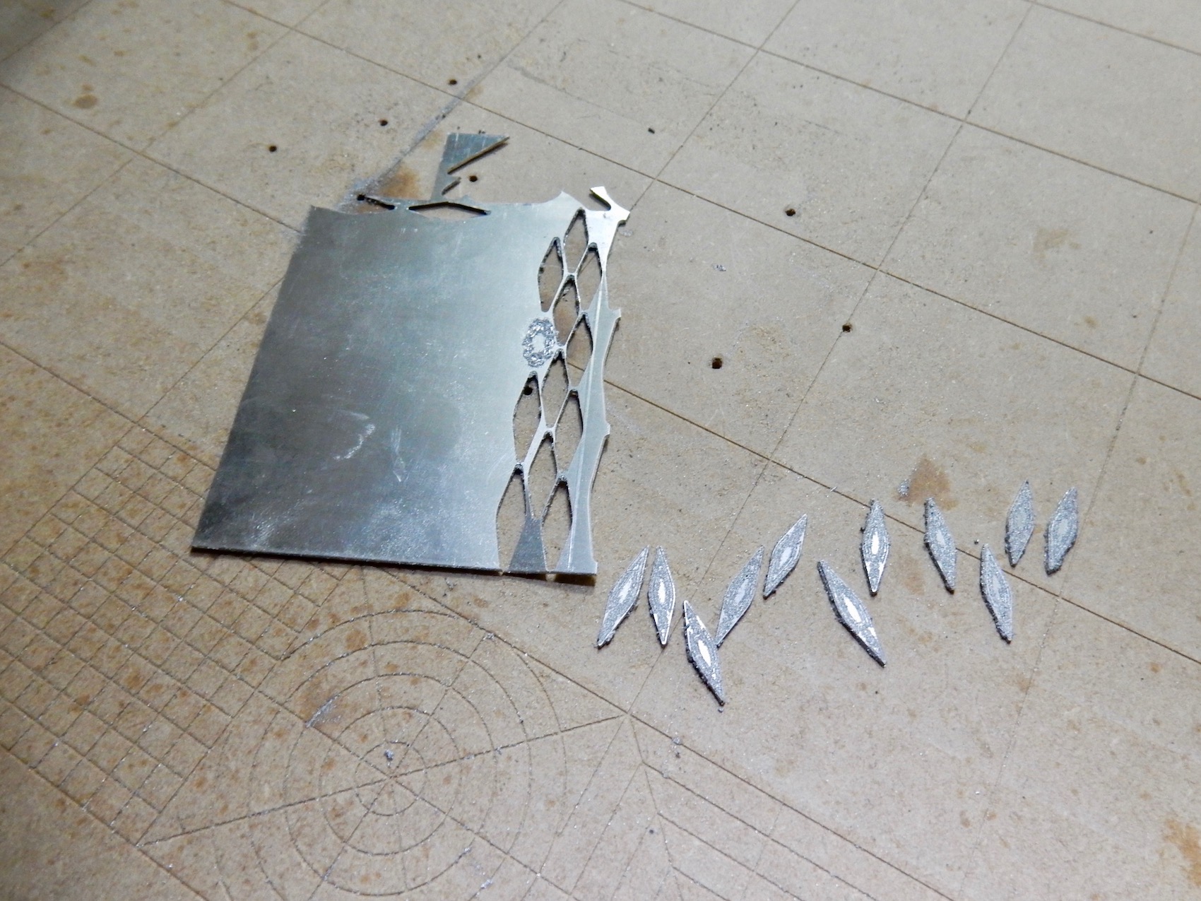
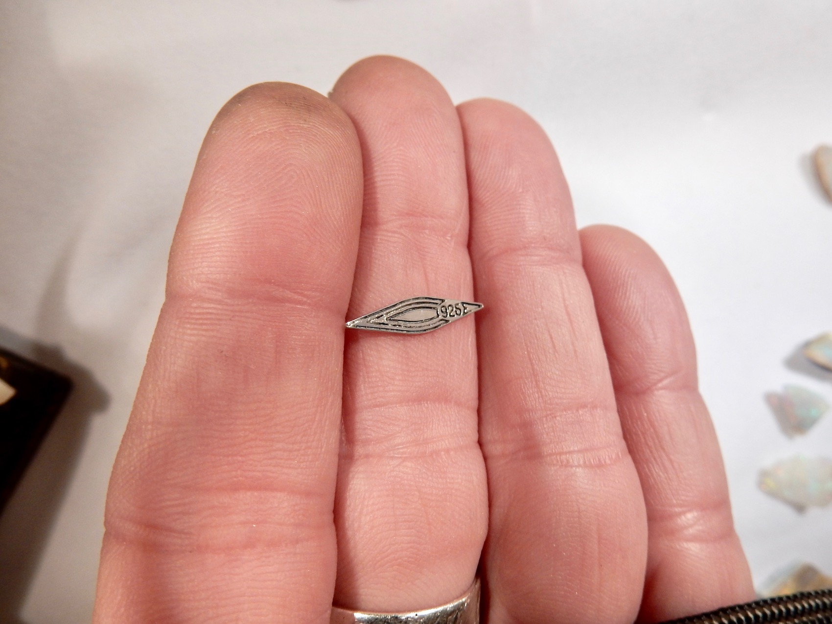
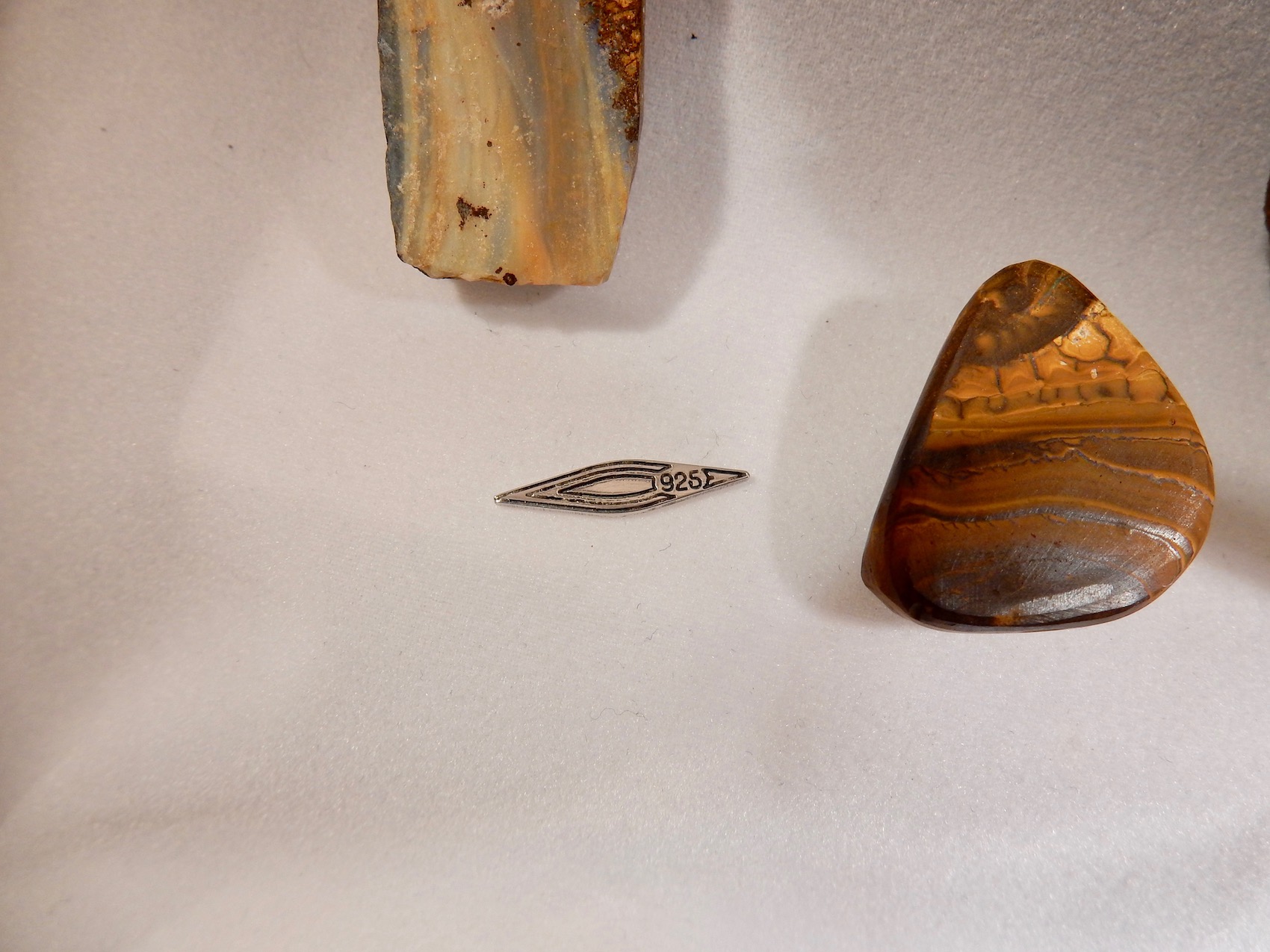
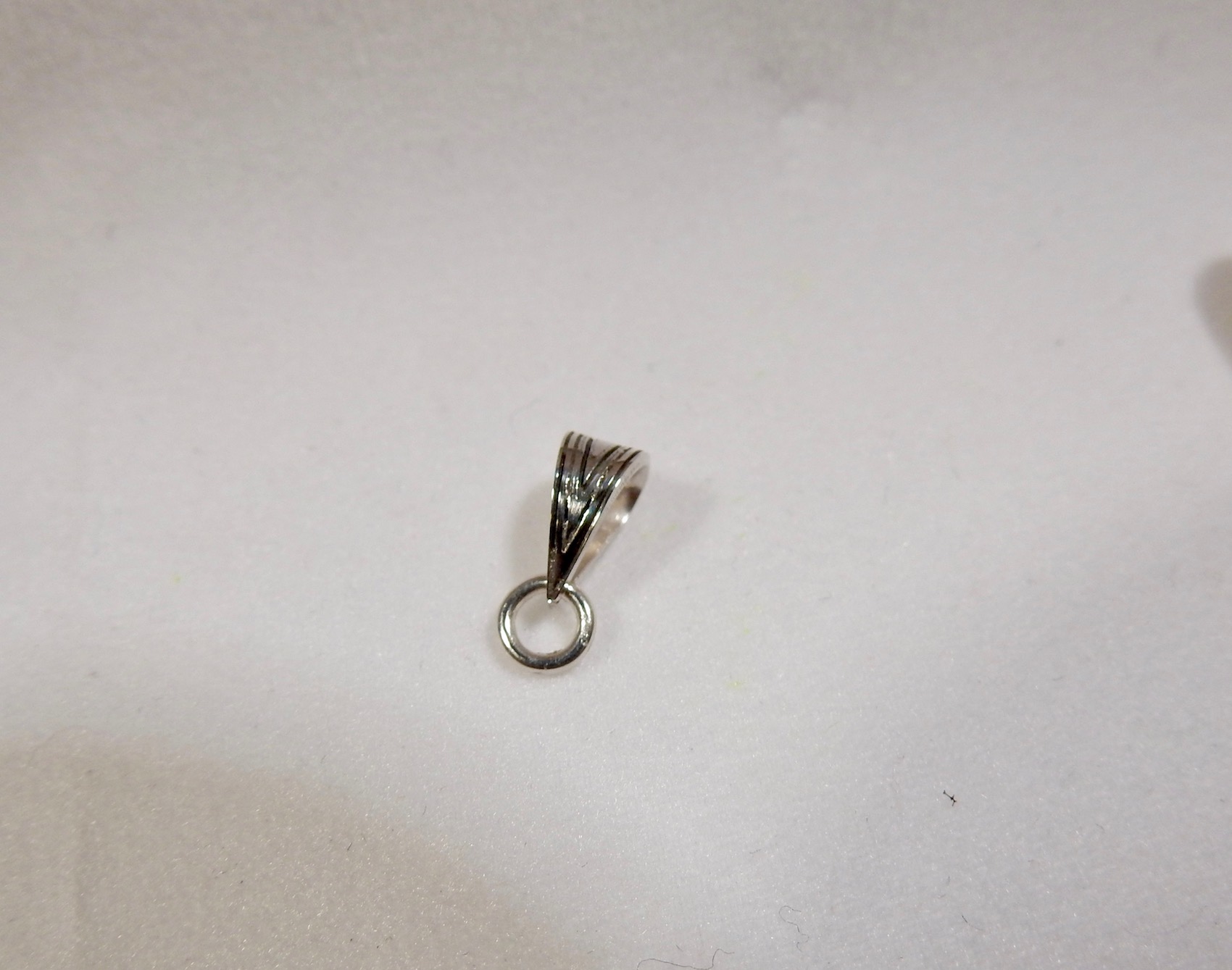
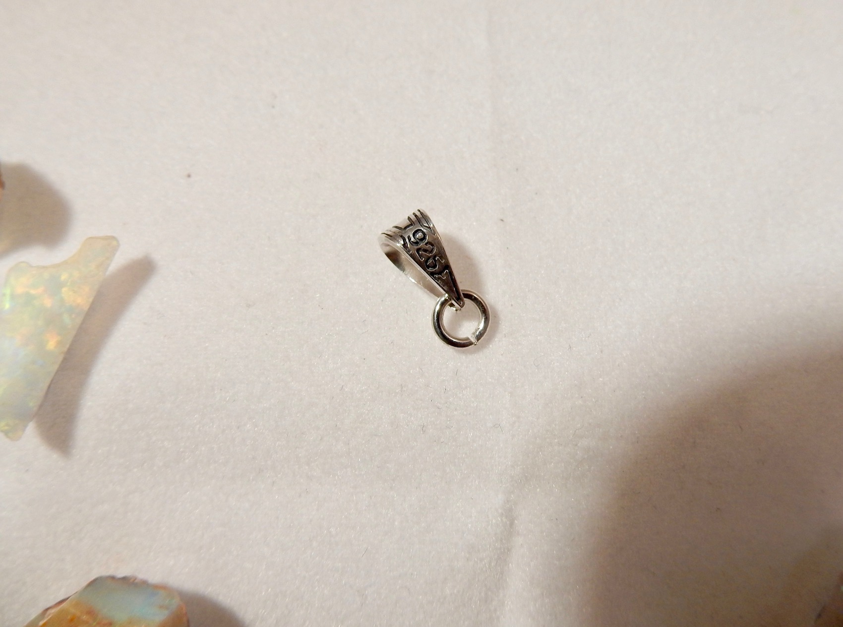
Engraving and cutting 925 Silver bails (07/06/2017)
It's been a few months since my last update. I haven't had much time to spend on the project , but I'm slowly getting somewhere :-)
- I decided to dump Fusion 360 for now and gave Aspire a shot, best move, I should have done that earlier. Both great software but Aspire is a lot more intuitive and adapted to my needs.
- Wood is forgiving and there is a lot of info on the net about it so it is not too difficult to 'guesstimate' starting points for feed-rates and spindle speeds, even using low end milling bits that don't come with manufacturer's specifications. A lot of info about Aluminum, plastics etc.. too even though it requires more trials and errors.
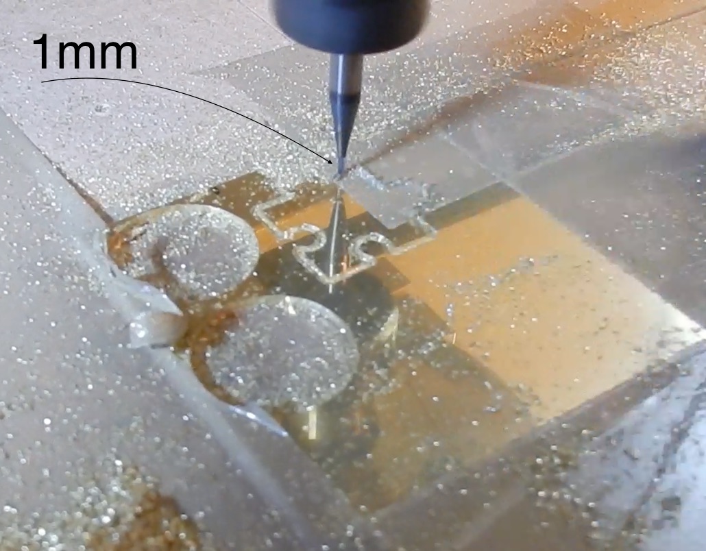
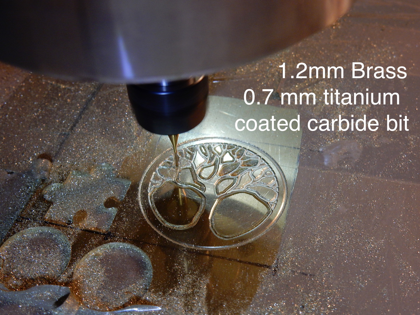
- My main headache still is when it comes to Sterling Silver with bits under 1mm . Where to get quality tools, with manufacturer's specs??? . Still plenty of breakage with 0.5mm flat ends and 0.1mm 'V' engravers. Just about to try some TIN coated carbide 0.7mm ,i'll see how that goes .
Below a few photos, engraving and cutting 0.8mm thick 925 silver to make my jewelry bails. I haven't tried 3D & 4th axis yet, maybe soon :-)
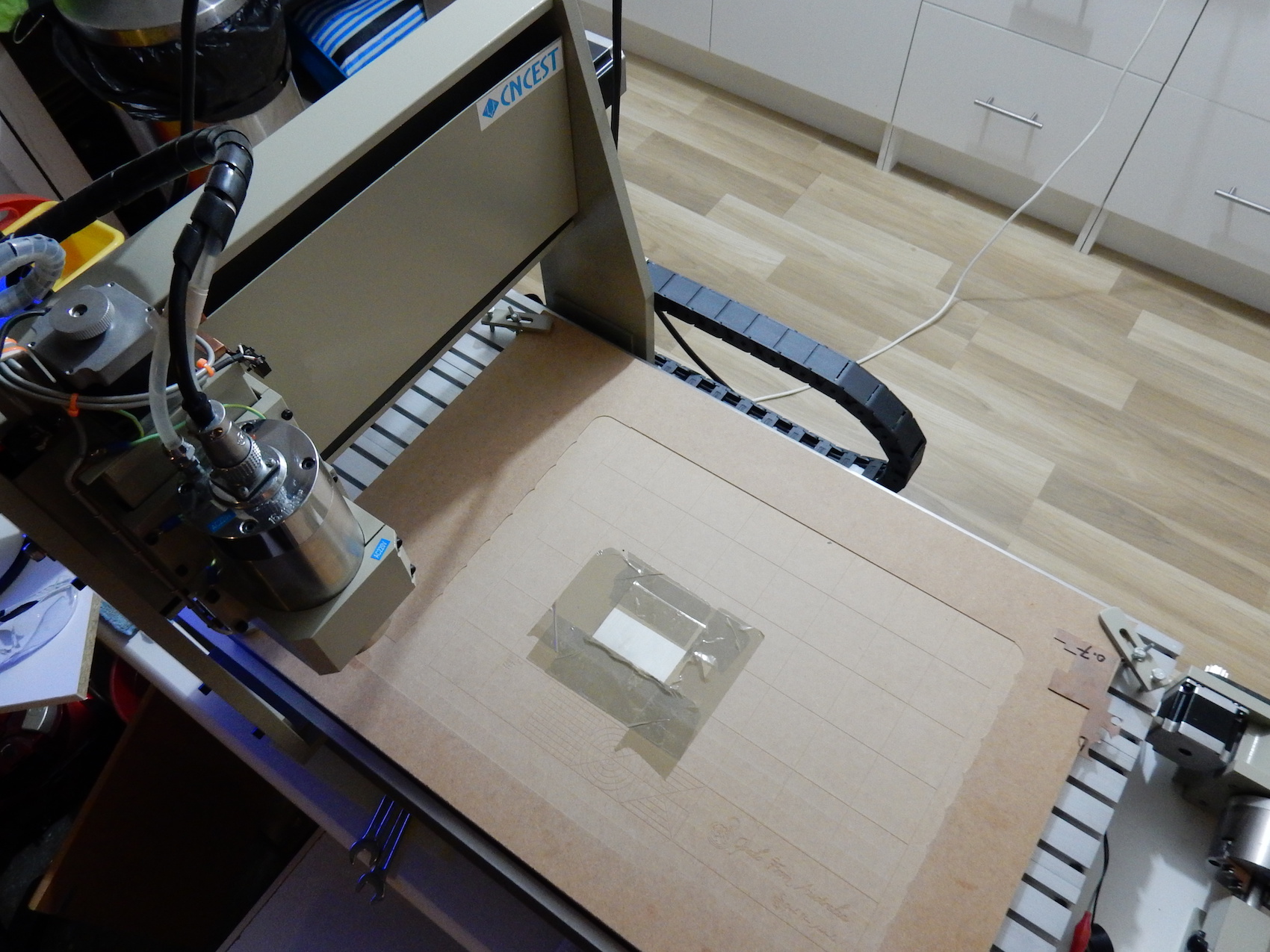
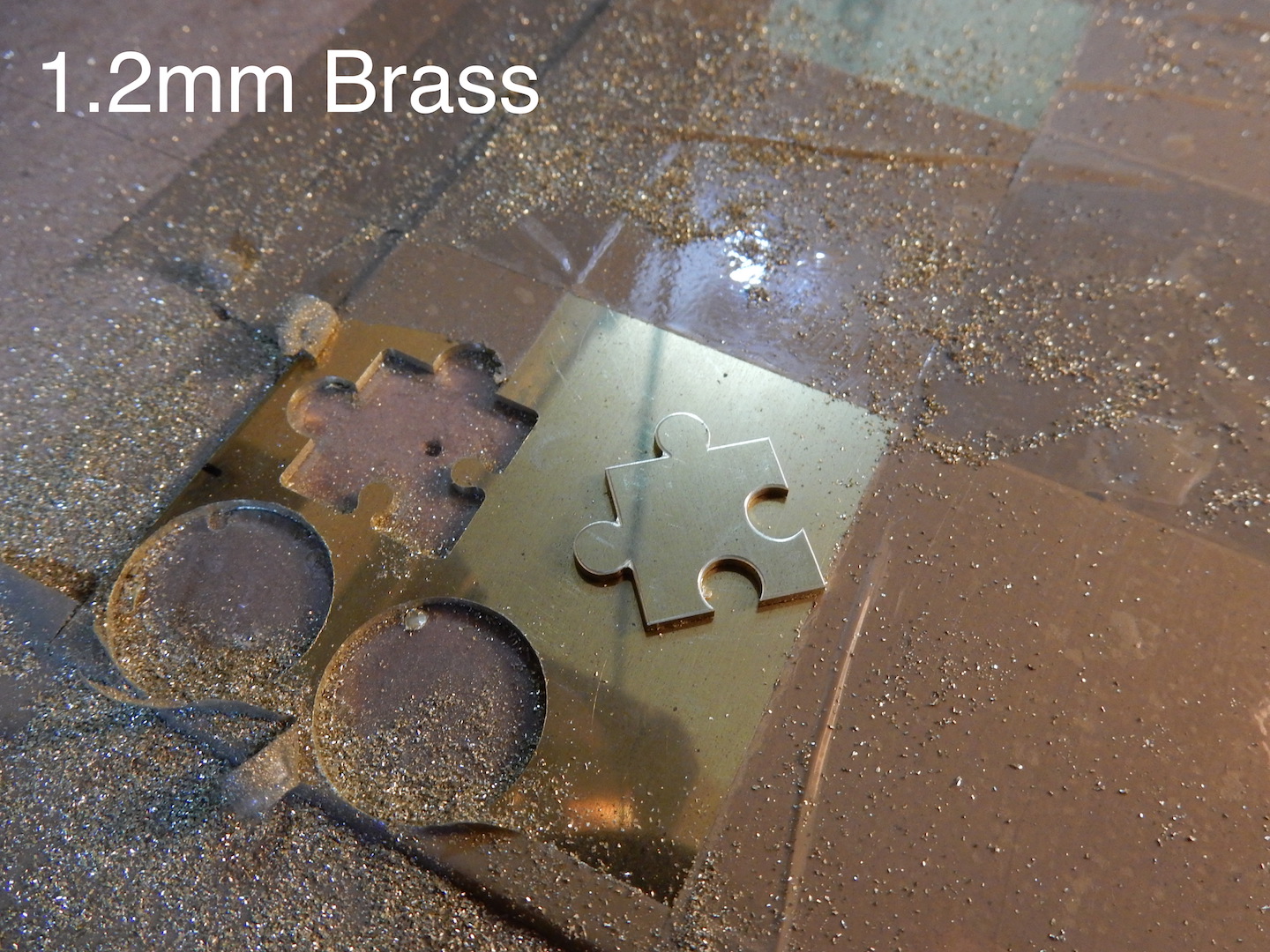
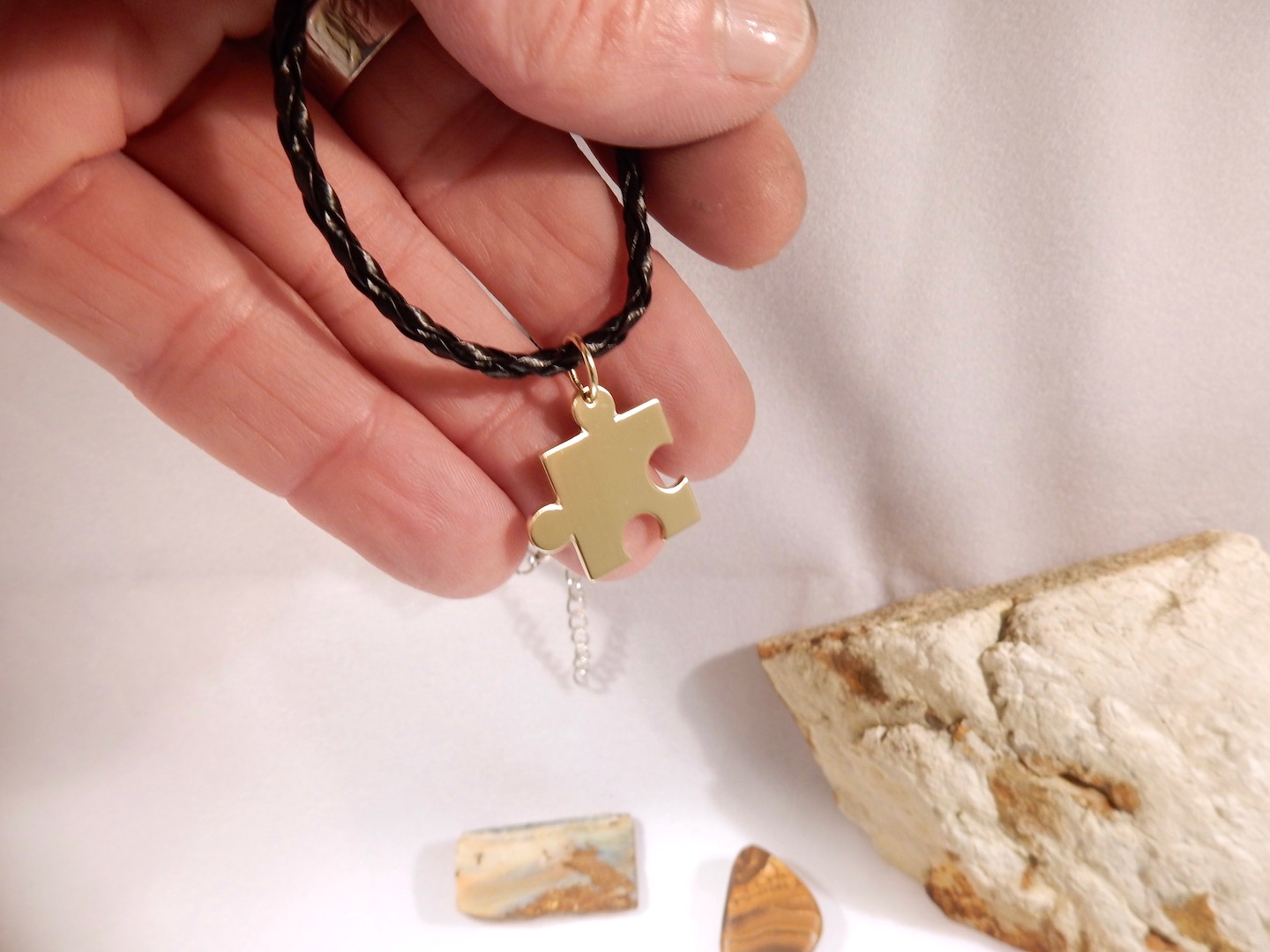
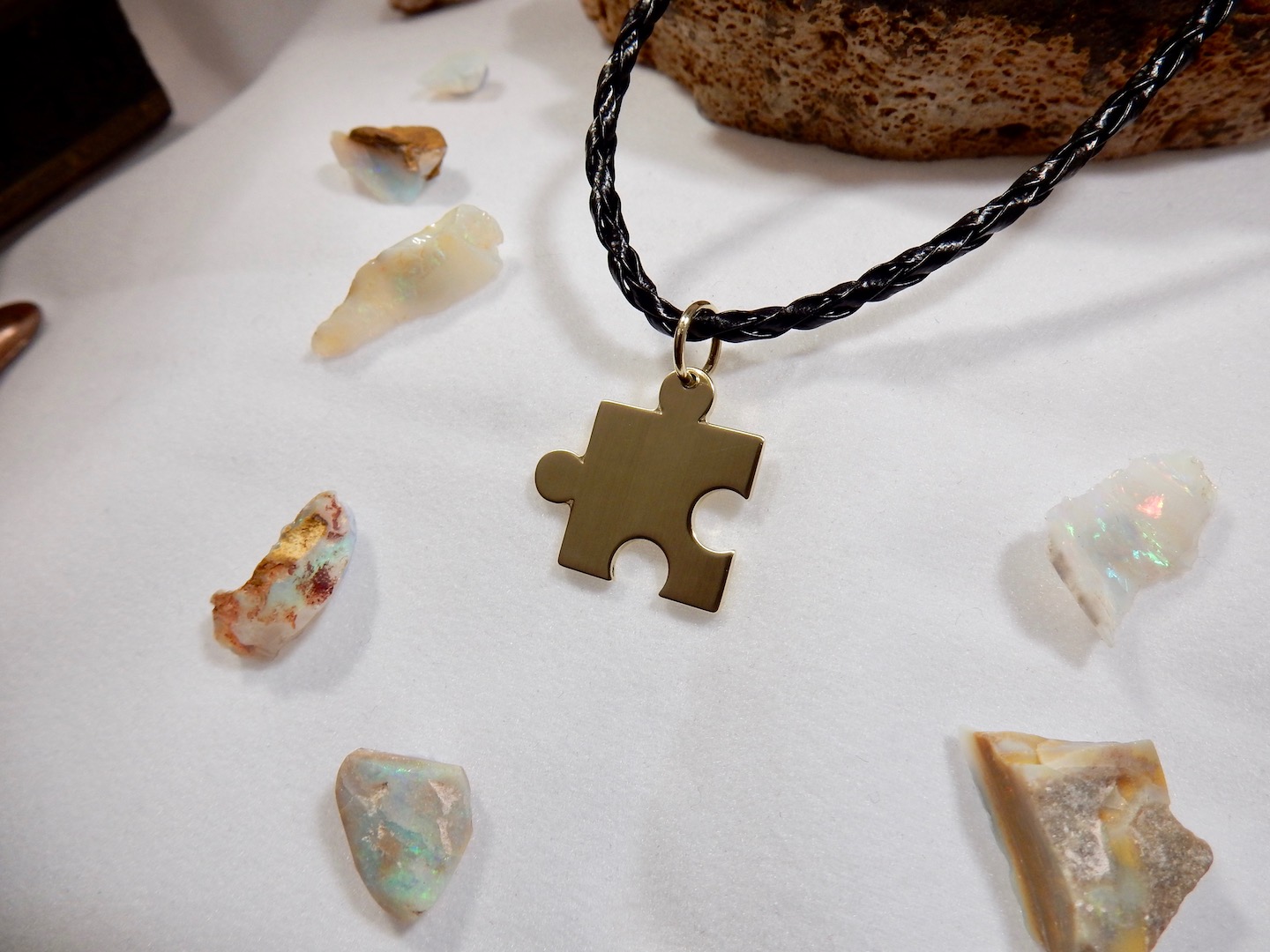
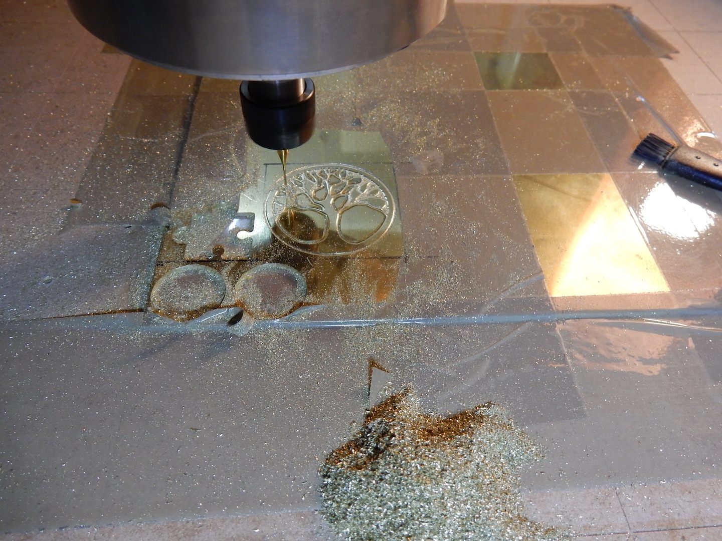
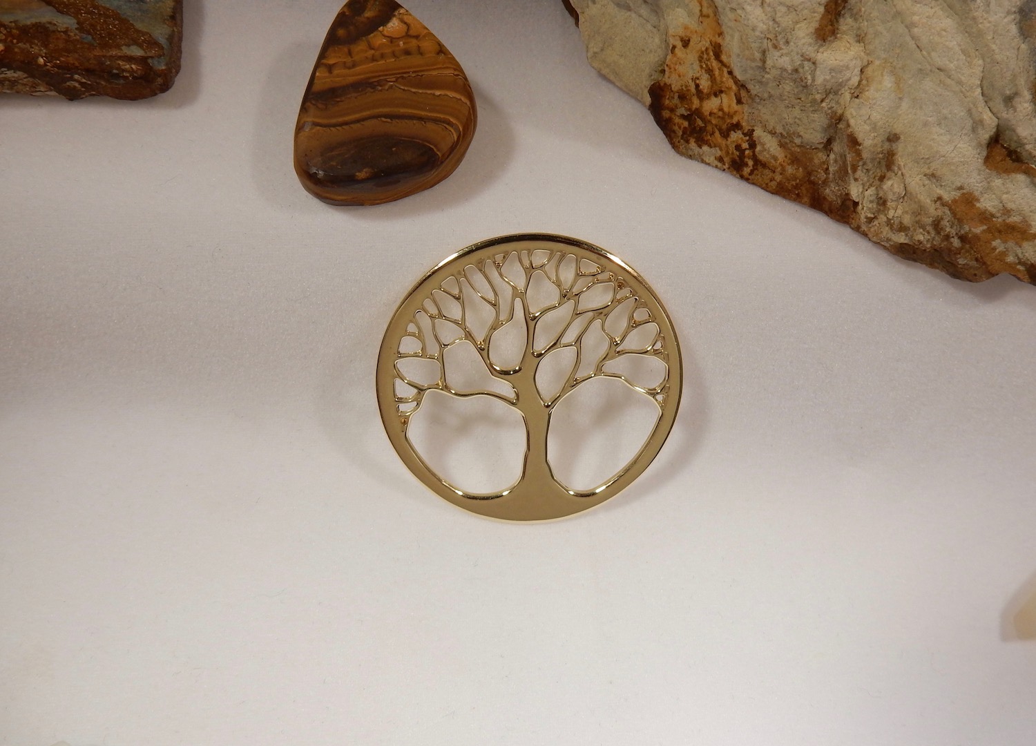
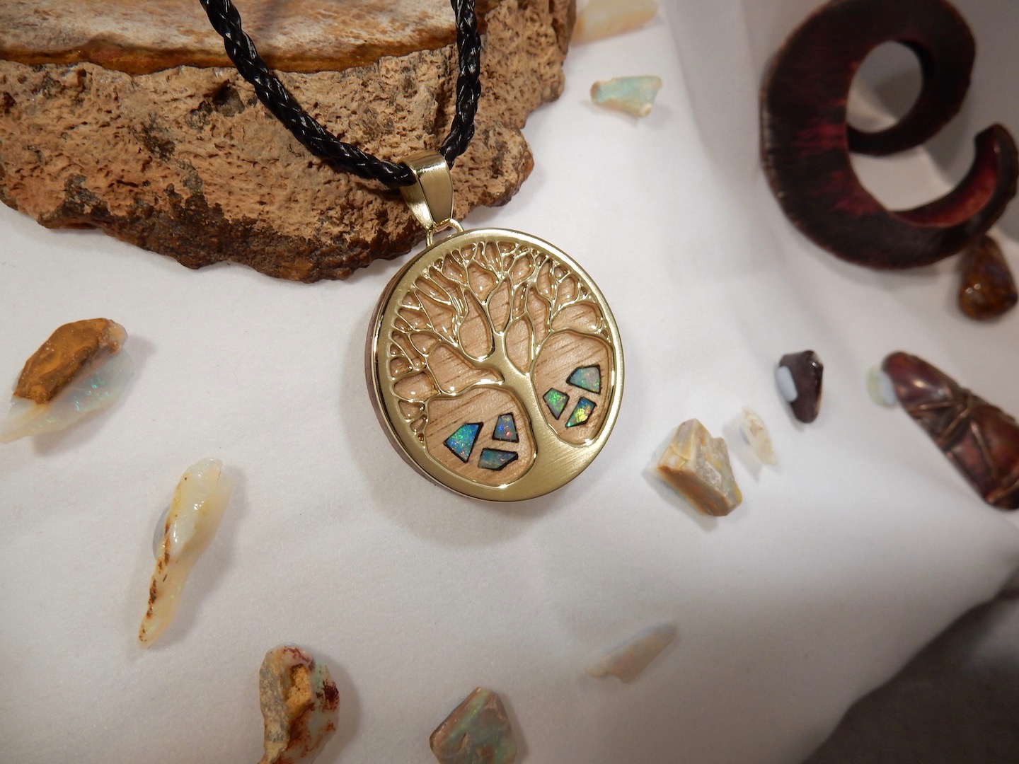
Brass cutting trials - Wood inlay pockets cutting (07/07/2017)
Having an other go at Fusion360 !! (10/09/2017)
Very happy with Aspire and disliked Fusion360 but I'm building some 'machine' prototype and will need to mill a few aluminum parts. I can now see some advantages with using Fusion360 over Aspire for this type of project.
And i found better tutorials, I'm slowly getting somewhere :-)
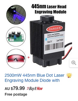
Attaching small laser module, for more engraving/cutting options. (10/10/2017)
.... this is postponed for now ......
I'm thinking starting with a cheap 2.5W for ~ $80 . Seems like it could be enough to go through 2mm acrylic, that would be handy to cut templates. Who knows , maybe 15W at a later stage ( ? )
with 2.5W .

Some 3rd party videos
Videos I've keept handy, either because there is a tip, 'feedrate' or watever. Or just things I'm planing to try when i get a chance.